Given the three phase circuit illustrated below. Two balanced loads and the capacitors are connceted to a 50 Hz balanced three phase line. The line to line voltage at the load is 500 Volts (rms). The line impedances are Zı=1.25+j1.25 N per phase. V, 500 Volt 1 Z=1.25+j1.25 Q 200 µF) LOAD 2 LOAD 1 5 kW pf-1.0 15 kW pf-0.707 (lag) c) Calculate the power factor seen from the source.
Given the three phase circuit illustrated below. Two balanced loads and the capacitors are connceted to a 50 Hz balanced three phase line. The line to line voltage at the load is 500 Volts (rms). The line impedances are Zı=1.25+j1.25 N per phase. V, 500 Volt 1 Z=1.25+j1.25 Q 200 µF) LOAD 2 LOAD 1 5 kW pf-1.0 15 kW pf-0.707 (lag) c) Calculate the power factor seen from the source.

Power System Analysis and Design (MindTap Course List)
6th Edition
ISBN:9781305632134
Author:J. Duncan Glover, Thomas Overbye, Mulukutla S. Sarma
Publisher:J. Duncan Glover, Thomas Overbye, Mulukutla S. Sarma
Chapter2: Fundamentals
Section: Chapter Questions
Problem 2.51P: A three-phase line with an impedance of (0.2+j1.0)/ phase feeds three balanced three-phase loads...

Related questions

Question
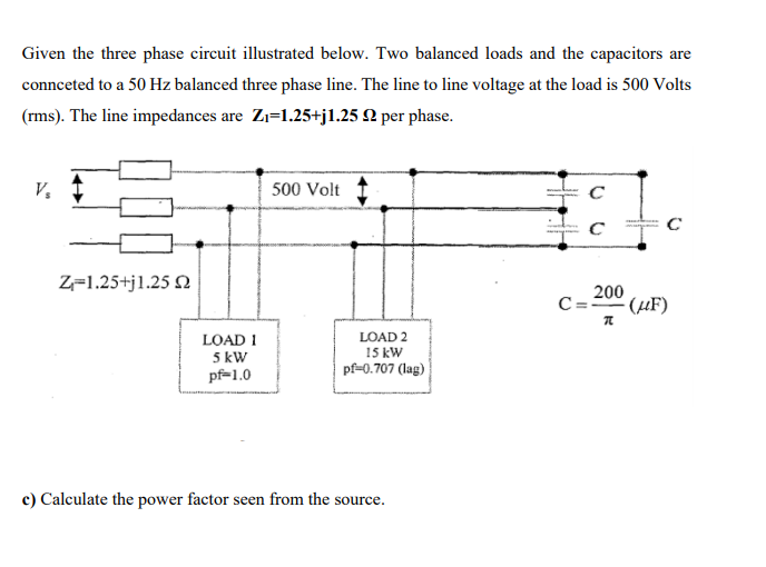
Transcribed Image Text:Given the three phase circuit illustrated below. Two balanced loads and the capacitors are
connceted to a 50 Hz balanced three phase line. The line to line voltage at the load is 500 Volts
(rms). The line impedances are Zı=1.25+j1.25 N per phase.
V.
500 Volt
C
Z=1.25+j1.25 N
200
C=20" (µF)
LOAD 2
LOAD 1
5 kW
pf-1.0
15 kW
pf-0.707 (lag)
c) Calculate the power factor seen from the source.
Expert Solution
This question has been solved!
Explore an expertly crafted, step-by-step solution for a thorough understanding of key concepts.

Step by step
Solved in 2 steps with 1 images

Knowledge Booster


Learn more about
Need a deep-dive on the concept behind this application? Look no further. Learn more about this topic, electrical-engineering and related others by exploring similar questions and additional content below.Recommended textbooks for you
Power System Analysis and Design (MindTap Course …
Electrical Engineering
ISBN:
9781305632134
Author:
J. Duncan Glover, Thomas Overbye, Mulukutla S. Sarma
Publisher:
Cengage Learning
Power System Analysis and Design (MindTap Course …
Electrical Engineering
ISBN:
9781305632134
Author:
J. Duncan Glover, Thomas Overbye, Mulukutla S. Sarma
Publisher:
Cengage Learning