heaves or when its effective stress is before the bottom of the saturated clay clay. How deep can the excavation proceed zero. Problem: From the figure shown: h=1.5m 1.5m G-2:68
Q: Example 1: In the Figure below, a hydraulic structure built on fine sand (C, = 15). Determine (a)…
A:
Q: A 10-m-thick layer of stiff saturated clay is underlain by a layer of sand Shown in the figure. The…
A: As per authoring guidelines, if the question number is not specified, the first question or three…
Q: Water is flowing through three soil layers as shown in Fig. Q2. The cross-section is a square with…
A:
Q: Assume some demand rates in the hydraulic network analysis. Explain briefly
A: Introduction- Water supply system (WSS)refers to a system for collecting, storing, and transporting…
Q: in figure below, a flow net is showing undemeath a reinforced concrete dam the permeability (k ) of…
A: The flow of fluid includes movement of an unbalanced fluid. As long as unequalled forces are in…
Q: Solve for the ratio of equivalent hydraulic conductivity with the following given: h1 = 2 m h2 = 2.5…
A:
Q: Figure Ql shows a 1D flow through a two layers soil column. The soil properties and cross-sectional…
A: In soil due to its height, there will be stress that is known as the total stress in the soil that…
Q: 4. A canal is cut into a soil with a stratigraphy shown in the figure below. A flow takes place…
A: Given data in question Layers depth and permeability To find out Physical meaning of permeability…
Q: (a) Calculate and draw the active earth pressure distribution acting on the smooth wall shown in…
A:
Q: 1.5 m 0.7 m 1 m A 2 m B Valve (open) Inflow - Sand
A:
Q: Refer to Problem 8.4. Using the flow net drawn, calculate the hydraulic uplift force at the base of…
A: Solution: The Flow net body diagram for the figure : The seepage loss can be calculated…
Q: ) a. Consider the upward flow of water through a layer of sand in a [Seepage] (** tank shown below.…
A:
Q: Question 1: * A 300 mm diameter test well penetrates a 27 m thick sand layer below the static water…
A: Given Data: Pumping =50 liters/s b=27 m r1=50 m r2=100 m S1=1 m S2=0.5 m Static water table=Confined…
Q: 4. Is Turbulent Flow Possible? Water flows through sand with an average particle size of 0.70 mm.…
A: given that is Average particle size =0.70mm Water temperature at sub surface 150C…
Q: = 370 mm A = 145 cm^2 h = 340 mm Water collected in 3 min Q = 580 cm^3 Void ratio of sand e= 0.66…
A:
Q: Two soil layers are shown in the figure. The soils have the same cross section area of 0.2 m2; and…
A:
Q: Water is flowing through three soil layers, as shown in the following figure. The cross-section is a…
A:
Q: A 500 m long levee made of compacted clay impoundswater in a reservoir as shown in attached Figure…
A: The given data is as follows: Length of levee=500 mThickness of sand seam=1 mInclination of sand…
Q: A 25 m thick layer of clay with a saturated unit weight of 21 kN/m³ is underlain by a layer of sand,…
A:
Q: unconfined aquifer underlies confined aquifer figure. An a shown in the a. Compute coefficient of…
A: To determine: equivalent coefficient of permeability in horizontal direction hydraulic gradient…
Q: 8.5 For the hydraulic structure shown in Figure 8.19, draw a flow net for flow through the permeable…
A: Problem 8.5:The value of hydraulic conductivity (k) is 0.002 cm/sec.Refer given Figure; the head…
Q: 7.22 Refer to Figure 7.24. The following data were collected during the field per- meability…
A:
Q: The figure below shows the layers of soil in a tube 100 mm x 100 mm in cross section. Water is…
A:
Q: Q.2 (c) A homogeneous anisotropic embankment dam section is shown in the figure, the coefficient of…
A:
Q: 3. A layered soil deposit is shown in the figure below with anisotropic values of the coefficient of…
A:
Q: For the dam spillway shown in Figure 1, draw a flownet at a scale of 1 inch = 10 meters. Using this…
A: The values and diagram given in the question are as follows Permeability(K)=1.8*10-4 cm/sec…
Q: Based on the shown image, compute the hydraulic radius. 28 in 2 in typical 8 in 14 in water
A: Hydraulic Radius: Hydraulic radius R is a measure of flow efficiency, is defined as the ratio of…
Q: 4. A canal is cut into a soil with a stratigraphy shown in the figure below. A flow takes place…
A: Given data in question Permeability of all the layers Depth of canal 3 m Depths of various layers…
Q: A well was constructed to pump water from a confined aquifer. Two observation wells were constructed…
A: The given data is shown below: Distances=350 m and 800 mDrawdowns=1.6m and 7.8mDiameter of test…
Q: 1. A soil sample 15 cm in diameter is placed in a tube 3 m long. A constant supply of water is…
A: We have to find the value of hydraulic gradient, flow rate, average velocity, seepage velocity if…
Q: The dam shown has a base of which 2 m. below the ground surface. The pressure distribution diagram…
A:
Q: For the loaded area shown in figure below: 1- Draw the distribution of total, effective, and pore…
A:
Q: 19. Given the following set of data representing the hydraulic conductivity of core samples from the…
A: Given,
Q: P1: Consider the upward flow of water through a layer of sand in a tank as shown in Figure. For the…
A: Solution: Given Data: void ratio e=0.52specific gravity=2.67 Saturated unit weight of…
Q: From the figure shown, the thickness of permeable layer is 1.1m making an angle of 14 degrees with…
A:
Q: A fine sand sample is placed into a permeameter that supplies a constant head of 100 cm of water.…
A:
Q: Refer to Problem 8.4. Using the flow net drawn, calculate the hydraulic uplift force at the base of…
A: Given information:
Q: For the hydraulic structure shown below, draw a flow net for flow through the permeable layer and…
A: Given: Coefficient of permeability Total head Number of flow lines Number of equipotential lines…
Q: SITUATION 3 A confined aquifer shown in the figure has a hydraulic conductivity of 48m/day with…
A:
Q: 5. Find hydraulic conductivity k in engineering applications. 7.17 Figure 7.35 shows the cross…
A: To Find :- Hydraulic Conductivity of Sand Layer.
Q: Example 2: A soil sample with 10 cm in diameter is placed in a tube 1 m long . A constant supply of…
A: The given data is: Diameter of soil sample (d) = 10 cm Length of sample (L) = 1 m Average amount of…
Q: Question 1: * Two observation wells have been constructed in the formation shown. The flow rate is…
A:
Q: The figure below shows the zone of capillary rise within a clay layer above the groundwater table.…
A:
Q: A well is fully penetrated into a 27 m thick layer of sand which is underlain by a rock layer below…
A: To find Coefficient of permeability Rate of discharge if k = 1.15 cm /s
Q: 3. (Bonus question) In the experimental setup shown in Figure 3, water flows through soils 1 and 2…
A:
Q: A 10-m-thick layer of stiff saturated clay is underlain by a layer of sand (as shown in Figure).The…
A:
Q: The cross-section of an earth dam is shown in figure below. Assuming that the water level remains…
A: Solution: Given data: Width of earth dam=300 mWater level remain constant at 35m kx=8.3×10⁻⁷ m/skz=…
Q: Question 4.8 Consider a layered reservoir consisting of three alternating layers 1 m thick and 1 m…
A: A layered reservoir consists of 3 layers. each layer is 1m thick and 1m long Permeabilities and…
Q: A borehole log profile in a construction project is shown in the figure. The proposed construction…
A: Given : Net stress, σnet = 12 kN/m3Unit weight of water, γw = 9.81 kN/m3…
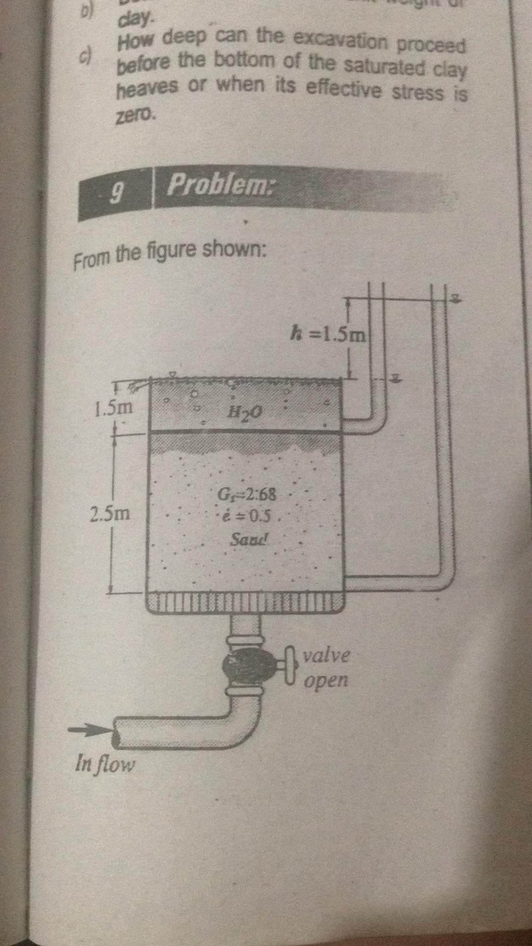
9. From the figure shown: (See picture below)
Cross-sectional area = 0.6m2
Hydraulic Conductivity of sand = 0.1 cm/sec
- What is the rate of upward seepage of water? (Answer: 360 cm3/sec)
- What would be the critical hydraulic gradient? (Answer: 1.12 m)
- What value of h to cause boiling? (Answer: 2.8 m)
Trending now
This is a popular solution!
Step by step
Solved in 2 steps with 2 images
- A deposit of cohesionless soil with a permeability of 0.3 mm/s has a depth of 12 m with impervious ledge below. A sheet pile wall is driven into this deposit to a depth of 8 m. The wall extendsabove the surface of the soil, and a 3 m depth of water acts on one side. Sketch the flow net and determine the seepage quantity. Provide a diagram a.600 ml/s/meter length b.300 ml/s/meter length c.900 ml/s/meter length d.1200 ml/s/meter length3.A half-closed clay layer is 8 m thick and it can be assumed that cv ¼ ch. Verticalsand drains 300 mm in diameter, spaced at 3 m centres in a square pattern, areto be used to increase the rate of consolidation of the clay under the increasedvertical stress due to the construction of an embankment. Without sand drainsthe degree of consolidation at the time the embankment is due to come into usehas been calculated as 25%. What degree of consolidation would be reachedwith the sand drains at the same time?An embankment consists of clay fill for which c=25 kPa and angle of internal friction is 260 9from consolidated undrained test with pore pressure measurement) The weight of fill per unit volume is 18.64 kN/m3. Compute the stress in kPa at depth of 20 m. Show free body diagram a.21.6 b.372.8 c.192.8 d.62.5
- If there is a layer of sand (lower layer) under artesian pressure (causes upward flow), calculate the excavation height H so that a negative effective stress is not generated at point A and therefore the heaving of the soil at that point. Use a unit weight of water w of 62.43 lb/ft3. Note: In this example we make a similarity with the permeameter with upward flow, therefore, H1=0 since from the bottom of the excavation (Na) upwards it remains dry (pumping is done), H2= 20ft-H, h=12ft-H2.The soil has a void ratio of 0.4 and G=2.75. h1=1.5m and h2=3m. Determine the effective unit weight of the sand in kN/cum. Determine the effective stress at pt. A in kPa. Determine the hydraulic gradient of sand for quick condition. Please answer this asap. For upvote. Thank you very muchAn embankment consists of clay fill for which c=25 kPa and angle of internal friction is 260 9from consolidated undrained test with pore pressure measurement) The weight of fill per unit volume is 18.64 kN/m3. Compute the stress in kPa at depth of 20 m. a. 192.8 b. 62.5 c. 21.6 d. 372.8
- Determine the consolidation settlement ofthe 4-m thick clay layer shown in the figurethat will result from the load carried by thefooting measuring 3 m x 1.5 m in the figure.Assume the clay to be normally consolidatedand the load of footing results to an increasein pressure of 23.2 kPa, 12.22 kPa, and 6.1kPa at the top, mid-height, and bottomportion, respectively of the clay layer.a) Calculate the overburden pressure at thebase of the footing in kPab) Calculate the initial effective stress at themid-height of the clay layerc) Calculate the consolidation settlement ofthe clay layerA single anchor slab is shown in Figure P14.12. Here, H = 0.9 m, h = 0.3 m, γ = 17 kN/m3, and Φ' = 32º. Calculate the ultimate holding capacity of the anchor slab if the width B is (a) 0.3 m, (b) 0.6 m, and (c) = 0.9 m.An exploratory drill hole was made in a stiff saturated clay having a moisture content of 38.9% and Gs = 2.34 as shown in the figure. The sand layer underlying the clay was observed to be under artesian pressure. Water in the drill hole rose to a height of 13.8 ft above the top of sand layer. If an open excavation is to be made in the clay, determine the (a) unit weight of the clay, and the (b) maximum cut before the bottom heaves.
- An oil tank is to be sited on a soft alluvial deposit of clay. Below the soft clay is athick layer of stiff clay. It was decided that a circular embankment, 10 m diameter,with wick drains inserted into the soft clay would be constructed to preconsolidateit. The height of the embankment is 6 m and the unit weight of the soil comprisingthe embankment is 18 kN/m3. The following data are available: thickness of softclay = 7 m, ks = 1 × 10⁻¹⁰ m/s and Ch = 0.6 m2/yr. The desired degree ofconsolidation is 90% in 12 months. Determine the spacing of a square grid of thewick drains. Assume wick drain of size 100 mm × 3 mm and qw = 0.1 × 10⁻⁶ m3/s.The flow point distance is 4 m. Assume a half-closed system.A soil profi le consists of a clay layer underlain by a sandlayer, as shown in Figure P7.17. If a tube is inserted intothe bottom sand layer and the water level rises to 1 mabove the ground surface, determine the vertical effective stresses and porewater pressures at A, B, and C. IfKo is 0.5, determine the lateral effective and lateral totalstresses at A, B, and C. What is the value of the porewater pressure at A to cause the vertical effective stressthere to be zero?An exploratory drill hole was made in a stiff saturated clay, as shown in Figure 1, having a moisture content of 25% and Gs = 2.56. The sand layer underlying the clay was observed to be under artesian pressure. Water in the drill hole rose to a height of 3 m above the top of sand layer. If an open excavation is to be made in the clay. a.What is the maximum depth of excavation before the bottom heaves? b.What would be the required height of water inside the cut in order to ensure a factor of safety of 1.5?