Horizontal cantilever shart with disks is loaded by 2 concentrated forces. 1 F1 Given: 1=26cm; l,=32cm; n-27cm; r-10cm; F= 100N; F;= -250N. Find: absolute value of reactive moment (in N-m) applied at fixed point.
Horizontal cantilever shart with disks is loaded by 2 concentrated forces. 1 F1 Given: 1=26cm; l,=32cm; n-27cm; r-10cm; F= 100N; F;= -250N. Find: absolute value of reactive moment (in N-m) applied at fixed point.

Mechanics of Materials (MindTap Course List)
9th Edition
ISBN:9781337093347
Author:Barry J. Goodno, James M. Gere
Publisher:Barry J. Goodno, James M. Gere
Chapter5: Stresses In Beams (basic Topics)
Section: Chapter Questions
Problem 5.12.11P: A cylindrical brick chimney of height H weighs w = 825 lb/ft of height (see figure). The inner and...

Related questions

Question
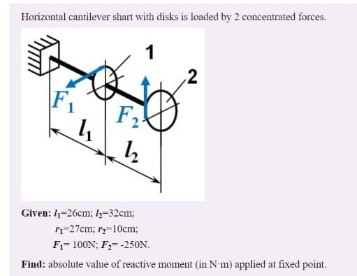
Transcribed Image Text:Horizontal cantilever shart with disks is loaded by 2 concentrated forces.
1
\F1
F2
Given: 1-26cm; l,-32cm;
n-27cm; r-10cm;
F1= 100N; F,= -25ON.
Find: absolute value of reactive moment (in N-m) applied at fixed point.
2.
Expert Solution
This question has been solved!
Explore an expertly crafted, step-by-step solution for a thorough understanding of key concepts.

Step by step
Solved in 2 steps with 2 images

Knowledge Booster


Learn more about
Need a deep-dive on the concept behind this application? Look no further. Learn more about this topic, mechanical-engineering and related others by exploring similar questions and additional content below.Recommended textbooks for you
Mechanics of Materials (MindTap Course List)
Mechanical Engineering
ISBN:
9781337093347
Author:
Barry J. Goodno, James M. Gere
Publisher:
Cengage Learning
Mechanics of Materials (MindTap Course List)
Mechanical Engineering
ISBN:
9781337093347
Author:
Barry J. Goodno, James M. Gere
Publisher:
Cengage Learning