The cantilever truss in the figure is hinged at D and E. Find the force in member AC. 1000 Ib 60 60• 30 C 3. lo lo00 16 |000 (6. 1372 Ib 1382 Ib 1732 lb O 1742 Ib
The cantilever truss in the figure is hinged at D and E. Find the force in member AC. 1000 Ib 60 60• 30 C 3. lo lo00 16 |000 (6. 1372 Ib 1382 Ib 1732 lb O 1742 Ib

Mechanics of Materials (MindTap Course List)
9th Edition
ISBN:9781337093347
Author:Barry J. Goodno, James M. Gere
Publisher:Barry J. Goodno, James M. Gere
Chapter1: Tension, Compression, And Shear
Section: Chapter Questions
Problem 1.3.10P: Find support reactions at 4 and Band then use the method of joints to find all member forces. Let b...

Related questions

Question
Statics and rigid bodies. Complete solution
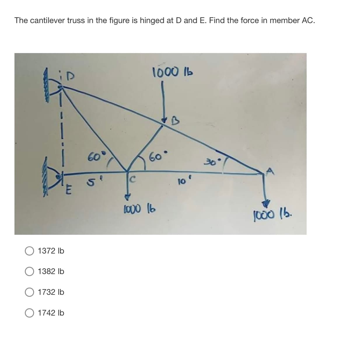
Transcribed Image Text:The cantilever truss in the figure is hinged at D and E. Find the force in member AC.
1000 1b
60
60
30°
3.
lo
1000 (6.
1372 Ib
1382 Ib
1732 Ib
O 1742 Ib
り
Expert Solution
This question has been solved!
Explore an expertly crafted, step-by-step solution for a thorough understanding of key concepts.

Step by step
Solved in 2 steps with 2 images

Knowledge Booster


Learn more about
Need a deep-dive on the concept behind this application? Look no further. Learn more about this topic, mechanical-engineering and related others by exploring similar questions and additional content below.Recommended textbooks for you
Mechanics of Materials (MindTap Course List)
Mechanical Engineering
ISBN:
9781337093347
Author:
Barry J. Goodno, James M. Gere
Publisher:
Cengage Learning
Mechanics of Materials (MindTap Course List)
Mechanical Engineering
ISBN:
9781337093347
Author:
Barry J. Goodno, James M. Gere
Publisher:
Cengage Learning