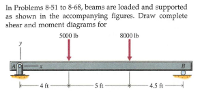
In Problems 8-51 to 8-68, beams are loaded and supported as shown in the accompanying figures. Draw complete shear and moment diagrams for 5000 lb 8000 Ib B. -4 ft 5 ft 4.5 ft
Q: Calculate the normal force, shear force and moment at point C for the given problem below
A: For the given beam, it is required to determine the normal force, shear force and bending moment at…
Q: Find the Shear Moment Diagram of the following problems using
A:
Q: Write shear and moment equations for the beams in the following problems. In each problem, let x be…
A: To determine the shear force and bending moment equations with diagrams.
Q: Problem 1 Compute the shear and moment diagram of the given figure below. Show complete values in…
A:
Q: Find the Shear Moment Diagram of the following problems using ONLY AREA METHOD.
A: Explanation: The stepwise procedure to draw SFD and BMD using area method is shown in the following…
Q: For the following beams, draw the simplified free-body diagram and below it the shear and bending…
A: Given: Let us consider the given image and Calculate the bending moments at the places of zero shear…
Q: Q-1. For the overhanging beam below; if the force (F) is equal to 400 lb: Draw the Free Body Diagram…
A: Consider vertically upward force & CW moment as (+)ve and vertically downward force & CCW…
Q: The beam shown in Figure P5.8-3 is a W16x31 of A99 steel and has continuous lateral support. The two…
A:
Q: Write shear and moment equations for the beams in the following problems. In each problem, let x be…
A: Draw the free-body diagram of the beam with x-x axis. Apply moment equilibrium about point A.…
Q: Rod (2) Bar (2) is simplified into a simple beam with a load in the middle of the rod. a. Draw a…
A:
Q: Problem 1: ( )Draw the shear force (V) and bending moment (M) diagrams for the beam AG below with…
A: The free body diagram of the beam is given below,
Q: Draw the shear and moment diagrams for the shaft.
A:
Q: Q.2) Draw the shear force and bending moment diagrams for the distributed load and two reaction…
A: draw the shear force and bending moment diagram.
Q: A simply supported beam subjected to three point loads as shown in the Figure force and bending…
A: Since the beam is symmetric, the reaction forces are equal in magnitude. From the vertical…
Q: If w = 25 kN/m., calculate the value of EIδ at 1 m. of the free end of the loaded beam as indicated…
A:
Q: An encase beam with uniform distributed load shown in following figure. W= 250N/m and L= 5m. Draw…
A:
Q: Draw the approximate shear and bending moment diagrams for the girders of the frames shown
A:
Q: In Figure Q3a, a beam is supported at A and C with a uniformly distributed load of 20 kN/m between A…
A: Draw a diagram for the beam showing support reactions at A and C. Here, RA and RC are the support…
Q: (5) Given the below 40 ft beam with the distributed load of 2 kips/ft and a point load of 16 kips:…
A:
Q: beams are loaded and supported as shown in the accompanying figure: Draw complete shear and moment…
A: The free-body diagram of the given beam is as shown below - since there is only point load acting…
Q: 8-14 Determine elastic positive bending-moment capacities around the horizontal axes for beams…
A: given; ⇒σ1=100MPa⇒σ2=140MPa
Q: Determine the values and draw the diagrams for shear force and bending moment due to the imposed…
A:
Q: For the following loading diagrams, find the shear and moment diagrams and calculate the maximum…
A: The free body diagram, of the beam is a follows: Calculate the moment about point A as follows:'…
Q: In Problem 4 (above), what is the shear force in section AB. Also, draw and label the shear diagram…
A: Solving question no 5 only Pls, repost the question with a specified question to be solved. As per…
Q: Figure 1 shows a 4 m length of a simply supported beam with a pinned support at and roller support…
A:
Q: For the figure shown below, compute the bending moment in section 1. Neglect the weights of the…
A:
Q: For the figure shown below, compute the bending moment in section 1. Neglect the weights of the…
A:
Q: Sample Problem 5/6: Draw the shear-force and bending-moment diagrams for the loaded beam and…
A:
Q: Consider the simple span prismatic beam shown below, pin supported at the left end and roller…
A:
Q: With the same loading conditions as in problem a, and to reduce the deflection at C, a roller…
A: Draw a free body diagram showing the reactions acting and each of the supports. Here, RA, RB, and…
Q: IN-CLASS EX. 5-6 • Draw the complete shearing force and bending moment diagrams for the beam. 800 N…
A:
Q: For the beams of problems 6.2-6.16, draw the shear force and bending moment diagrams and find the…
A: given overhanging beam as shown below
Q: A simply supported wood beam having a span length L=12ft is subjected to unsymmetrical point loads.…
A:
Q: Compute the shear and moment diagram of the given figure below. Show complete values in the…
A: TO find Shear and moment diagram
Q: For the frame shown in the figure , the bending moment at Bequals
A:
Q: In Problems 8-51 to 8-68, beams are loaded and supported as shown in the accompanying figures. Draw…
A: Consider the free body diagram as shown below for the given beam.
Q: Draw the shearing force and bending moment diagrams for the beam with an overhang subjected to the…
A: Given Data The load acting at B is: P1=14 kips The load acting at D is: P2=10 kips The UDL acting…
Q: Draw the shear and moment diagrams for the cantilever beam in Fig. 7-15a.
A:
Q: Draw the shear and moment diagrams for each beam shown in figu
A:
Q: 4) A simply-supported beam has a shear diagram shown in Figure 2. a) Draw the moment diagram based…
A:
Q: beams are loaded and supported as shown in the accompanying figure: Draw complete shear and moment…
A: Given: A simple supported beam To draw shear force and bending moment diagram
Q: 1. Compute the reactions at the supports using the tech- niques shown in Section 5-2. 2 Draw the…
A:
Q: Problem 5: Draw the shear and moment diagrams for the shaft in the figure below. The support A is a…
A:
Q: Problem 4: Draw the shear and moment diagrams for the cantilevered beam shown below. 600 lb 40 lb/ft…
A: First calculate the reactions. Then draw the diagrams.
Q: Draw the complete shearing force and bending moment diagram for the beam shown in the figure. Draw…
A:
Q: beams are loaded and supported as shown in the accompanying figure Draw complete shear and moment…
A: Draw the free-body diagram of the beam. Apply force equilibrium in a vertical direction.…
Q: beams are loaded and supported as shown in the accompanying figure Draw complete shear and moment…
A: Sign Convention for SFD 1) RUN ( Right Upward Negative) 2) RDP (Right Downward Positive) 3) LUP…
Q: A cantilever of length 5 m carries a of 4 KNm at the free end. Draw the shear force and bending…
A: Let w =UDL =2KN/m l =5m P = 4KN R = Reaction at fixed support =2X5+4 =14KN M= Moment at fixed…
Q: Problem#1 Draw the shear and bending diagram for the hanged beam shown below using section method…
A: Given length of the beam→L=4+2=6 m Uniform distributed load→w=6 KN/m Let consider vertical reaction…
Step by step
Solved in 2 steps with 1 images
- Repeat Problem 11.2-3 assuming that R= 10 kN · m/rad and L = 2 m.Solve Problem 11.3-3 for a W 10 × 45 steel column having a length L = 28 ft.Beam ABC is supported by a tie rod CD as shown. Two configurations are possible: pin support at A and downward triangular load on AB or pin at B and upward load on AB. Which has the larger maximum moment? First, find all support reactions; then plot axial force (N), shear (V), and moment (M) diagrams for ABC only and label all critical N, V, and M values. Label the distance to points where any critical ordinates are zero.
- A simply supported beam ABC is loaded at the end of a bracket BDE (see figure). Draw axial-force, shear-force, and bending-moment diagrams for ABC.Draw the shear and moment diagram for the textbook problem 6-8. Indicate the maximum moment from that diagram as your answer. Use kip-ft and include negative sign if applicable.For the figure shown below, compute the bending moment in section 1. Neglect the weights of the member. Note that point B is pin-connected.
- For the beams of problems 6.2-6.16, draw the shear force and bending moment diagrams and find the maximum shear force, maximum bending moment and point(s) of contraflexure (PCF).Calculate the reactions at the supports and obtain the shear force and bending moment diagrams for the following shaft using MD Solids software. The diameter of the shaft is 3.5433 inches and FA = 84.80 pounds-force.Figure 2 below shows a 12 m length of beam with a pinned support at A and rollersupport at C. The beam carries a uniformly distributed load (UDL) of 4 kN/m and aconcentrated load of 12 kN at B.a. Show the Free Body Diagram (FBD) of the beam then determine the reactionforce.b. Calculate the shear force, V. Draw Shear Force Diagram (SFD).c. Calculate the bending moment, M. Draw the Bending Moment Diagram (BMD).
- Figure 6 shows a beam of length 8 m, simply supported at each end, and loadedwith a point load of 60 kN and a uniformly distributed load of 30 kN/m over 6m of thebeam.A beam 19 ft in length has concentrated live loads of 6 kips and 9 kips at 5 ft and 13 ft, respectively, from the left-hand support. In addition, there is a uniformly distributed dead load of 1.2 kips/ft beginning 5 ft from the left support and continuing to the right support. Design the beam for flexure.For the beam shown below:Draw the free body diagram showing the reactions for each type of supportsknowing that the support on the left is a roller and on the right is a pin