In the figure below, a motor with power 150kw and speed of 2500 rpm is connected to shaft 1(by coupling) in a clockwise direction. Shaft 2 is connected to shaft 1 by gears 1 and 2. If 30% of the power is consumed by the gear3 and 9% by the pulley and 61% by the sprocket, draw torque diagrams for both shafts. If the pressure angle of the gears is 20 degrees to the x-axis, Calculate the reaction forces of the bearings and draw the bending moment diagrams for both shafts according to the information below: Lengths: AB=90mm/BC=GH=50mm/CD=HI=60mm/DE=IJ=80mm Diameters: dG1=dG2=47mm/dG3=20mm/ d(pulley)=35mm/d(sprocket)=40mm Motor Gear T(ew) LB BE Bearing KATAST (c Gear1 Sprocket Gear2 Ta Ofu shaft 5₂ Palley shaft2
In the figure below, a motor with power 150kw and speed of 2500 rpm is connected to shaft 1(by coupling) in a clockwise direction. Shaft 2 is connected to shaft 1 by gears 1 and 2. If 30% of the power is consumed by the gear3 and 9% by the pulley and 61% by the sprocket, draw torque diagrams for both shafts. If the pressure angle of the gears is 20 degrees to the x-axis, Calculate the reaction forces of the bearings and draw the bending moment diagrams for both shafts according to the information below: Lengths: AB=90mm/BC=GH=50mm/CD=HI=60mm/DE=IJ=80mm Diameters: dG1=dG2=47mm/dG3=20mm/ d(pulley)=35mm/d(sprocket)=40mm Motor Gear T(ew) LB BE Bearing KATAST (c Gear1 Sprocket Gear2 Ta Ofu shaft 5₂ Palley shaft2

Elements Of Electromagnetics
7th Edition
ISBN:9780190698614
Author:Sadiku, Matthew N. O.
Publisher:Sadiku, Matthew N. O.
ChapterMA: Math Assessment
Section: Chapter Questions
Problem 1.1MA

Related questions

Question
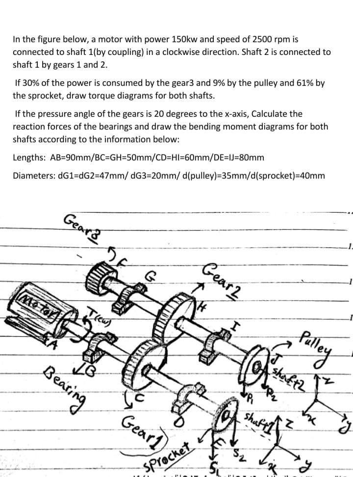
Transcribed Image Text:In the figure below, a motor with power 150kw and speed of 2500 rpm is
connected to shaft 1(by coupling) in a clockwise direction. Shaft 2 is connected to
shaft 1 by gears 1 and 2.
If 30% of the power is consumed by the gear3 and 9% by the pulley and 61% by
the sprocket, draw torque diagrams for both shafts.
If the pressure angle of the gears is 20 degrees to the x-axis, Calculate the
reaction forces of the bearings and draw the bending moment diagrams for both
shafts according to the information below:
Lengths: AB=90mm/BC=DGH=50mm/CD=HI=60mm/DE=IJ=80mm
Diameters: dG1=dG2=47mm/ dG3=20mm/ d(pulley)=35mm/d(sprocket)=40mm
Gears
Gear2
Tew)
shaftz
Bearing
Shaft
Gear1
SProcket
Expert Solution
This question has been solved!
Explore an expertly crafted, step-by-step solution for a thorough understanding of key concepts.

Step by step
Solved in 5 steps with 1 images

Knowledge Booster


Learn more about
Need a deep-dive on the concept behind this application? Look no further. Learn more about this topic, mechanical-engineering and related others by exploring similar questions and additional content below.Recommended textbooks for you
Elements Of Electromagnetics
Mechanical Engineering
ISBN:
9780190698614
Author:
Sadiku, Matthew N. O.
Publisher:
Oxford University Press

Mechanics of Materials (10th Edition)
Mechanical Engineering
ISBN:
9780134319650
Author:
Russell C. Hibbeler
Publisher:
PEARSON

Thermodynamics: An Engineering Approach
Mechanical Engineering
ISBN:
9781259822674
Author:
Yunus A. Cengel Dr., Michael A. Boles
Publisher:
McGraw-Hill Education
Elements Of Electromagnetics
Mechanical Engineering
ISBN:
9780190698614
Author:
Sadiku, Matthew N. O.
Publisher:
Oxford University Press
Mechanics of Materials (10th Edition)
Mechanical Engineering
ISBN:
9780134319650
Author:
Russell C. Hibbeler
Publisher:
PEARSON
Thermodynamics: An Engineering Approach
Mechanical Engineering
ISBN:
9781259822674
Author:
Yunus A. Cengel Dr., Michael A. Boles
Publisher:
McGraw-Hill Education

Control Systems Engineering
Mechanical Engineering
ISBN:
9781118170519
Author:
Norman S. Nise
Publisher:
WILEY

Mechanics of Materials (MindTap Course List)
Mechanical Engineering
ISBN:
9781337093347
Author:
Barry J. Goodno, James M. Gere
Publisher:
Cengage Learning

Engineering Mechanics: Statics
Mechanical Engineering
ISBN:
9781118807330
Author:
James L. Meriam, L. G. Kraige, J. N. Bolton
Publisher:
WILEY