INPUT DATA Recommended input power 300Watt Recommended PV modules 300w / Vmp > 34VDC / Voc < 5OVDC Maximum input DC voltage SOVDC Peak power tracking voltage 22-50VDC Operating voltage range 17-50VDC Min. / Max. Start voltage 22-50VDC Maximum DC short current 15A Maximum input current 9.8A
INPUT DATA Recommended input power 300Watt Recommended PV modules 300w / Vmp > 34VDC / Voc < 5OVDC Maximum input DC voltage SOVDC Peak power tracking voltage 22-50VDC Operating voltage range 17-50VDC Min. / Max. Start voltage 22-50VDC Maximum DC short current 15A Maximum input current 9.8A

Power System Analysis and Design (MindTap Course List)
6th Edition
ISBN:9781305632134
Author:J. Duncan Glover, Thomas Overbye, Mulukutla S. Sarma
Publisher:J. Duncan Glover, Thomas Overbye, Mulukutla S. Sarma
Chapter3: Power Transformers
Section: Chapter Questions
Problem 3.30P: Reconsider Problem 3.29. If Va,VbandVc are a negative-sequence set, how would the voltage and...

Related questions
Question
Most probably, the following table is the specifications of a
a. string inverter.
b. micro inverter.
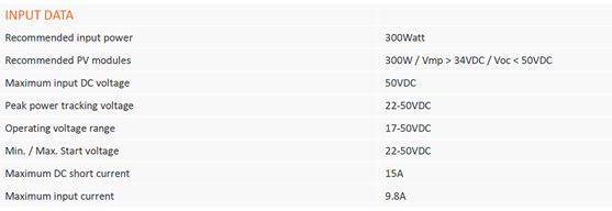
Transcribed Image Text:INPUT DATA
Recommended input power
300Watt
Recommended PV modules
300w / Vmp > 34VDC / Voc < 5OVDC
Maximum input DC voltage
SOVDC
Peak power tracking voltage
22-50VDC
Operating voltage range
17-50VDC
Min. / Max. Start voltage
22-50VDC
Maximum DC short current
15A
Maximum input current
9.8A
Expert Solution
This question has been solved!
Explore an expertly crafted, step-by-step solution for a thorough understanding of key concepts.

This is a popular solution!

Trending now
This is a popular solution!

Step by step
Solved in 3 steps with 2 images

Knowledge Booster


Learn more about
Need a deep-dive on the concept behind this application? Look no further. Learn more about this topic, electrical-engineering and related others by exploring similar questions and additional content below.Recommended textbooks for you
Power System Analysis and Design (MindTap Course …
Electrical Engineering
ISBN:
9781305632134
Author:
J. Duncan Glover, Thomas Overbye, Mulukutla S. Sarma
Publisher:
Cengage Learning
Power System Analysis and Design (MindTap Course …
Electrical Engineering
ISBN:
9781305632134
Author:
J. Duncan Glover, Thomas Overbye, Mulukutla S. Sarma
Publisher:
Cengage Learning