IV. Determine the maximum deflection of the of the following beams. 30k 12 ft 24 f = 1500 in*, E = 29 x 10“ psi. 15 kN 40 kN I = 2 x 10° mm* I = 3 x 10 mm A 6 m - 6 m E = 200 GPa
IV. Determine the maximum deflection of the of the following beams. 30k 12 ft 24 f = 1500 in*, E = 29 x 10“ psi. 15 kN 40 kN I = 2 x 10° mm* I = 3 x 10 mm A 6 m - 6 m E = 200 GPa

Mechanics of Materials (MindTap Course List)
9th Edition
ISBN:9781337093347
Author:Barry J. Goodno, James M. Gere
Publisher:Barry J. Goodno, James M. Gere
Chapter9: Deflections Of Beams
Section: Chapter Questions
Problem 9.3.16P: A simple beam with an overhang is subjected to d point load P = 6kN. If the maximum allowable...

Related questions

Question
With the use of area moment method
Transcribed Image Text:2/3
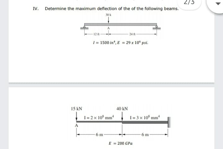
IV. Determine the maximum deflection of the of the following beams.
30 k
12 A
24 ft
1 = 1500 in", E = 29 x 10“ psi.
15 kN
40 kN
I = 2 x 10 mm*
I = 3 x 10* mmª
A
-6 m
6 m
E = 200 GPa
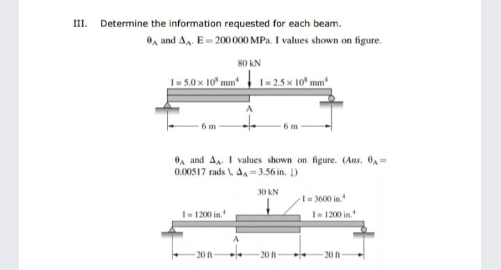
Transcribed Image Text:III. Determine the information requested for each beam.
O, and AA. E= 200 000 MPa. I values shown on figure.
80 kN
I = 5.0 × 10* mm*
I = 2.5 x 10° mm*
6 m
6 m
OA and AA. I values shown on figure. (Ans. 0A=
0.00517 rads \, AA = 3.56 in. Į)
30 kN
I = 3600 in.*
I = 1200 in."
I= 1200 in."
20 ft-
- 20 ft
- 20 ft
Expert Solution
This question has been solved!
Explore an expertly crafted, step-by-step solution for a thorough understanding of key concepts.

Step by step
Solved in 4 steps with 9 images

Knowledge Booster


Learn more about
Need a deep-dive on the concept behind this application? Look no further. Learn more about this topic, mechanical-engineering and related others by exploring similar questions and additional content below.Recommended textbooks for you
Mechanics of Materials (MindTap Course List)
Mechanical Engineering
ISBN:
9781337093347
Author:
Barry J. Goodno, James M. Gere
Publisher:
Cengage Learning
Mechanics of Materials (MindTap Course List)
Mechanical Engineering
ISBN:
9781337093347
Author:
Barry J. Goodno, James M. Gere
Publisher:
Cengage Learning