Nodal Analysis Example : Write the nodal equations for the circuit shown; 102 js Reference nsdet Solution :We have tw o independent node 1 and 2 , so two equatione have to be written : Node 1 (4+j4) is 4+j4 10 j5 Node 2 %3D 5 6-j8 From thece two equetione, the unknown voltages V, and V, must be determined.
Nodal Analysis Example : Write the nodal equations for the circuit shown; 102 js Reference nsdet Solution :We have tw o independent node 1 and 2 , so two equatione have to be written : Node 1 (4+j4) is 4+j4 10 j5 Node 2 %3D 5 6-j8 From thece two equetione, the unknown voltages V, and V, must be determined.

Power System Analysis and Design (MindTap Course List)
6th Edition
ISBN:9781305632134
Author:J. Duncan Glover, Thomas Overbye, Mulukutla S. Sarma
Publisher:J. Duncan Glover, Thomas Overbye, Mulukutla S. Sarma
Chapter2: Fundamentals
Section: Chapter Questions
Problem 2.17MCQ: Consider the load convention that is used for the RLC elements shown in Figure 2.2 of the text. A....

Related questions
Question
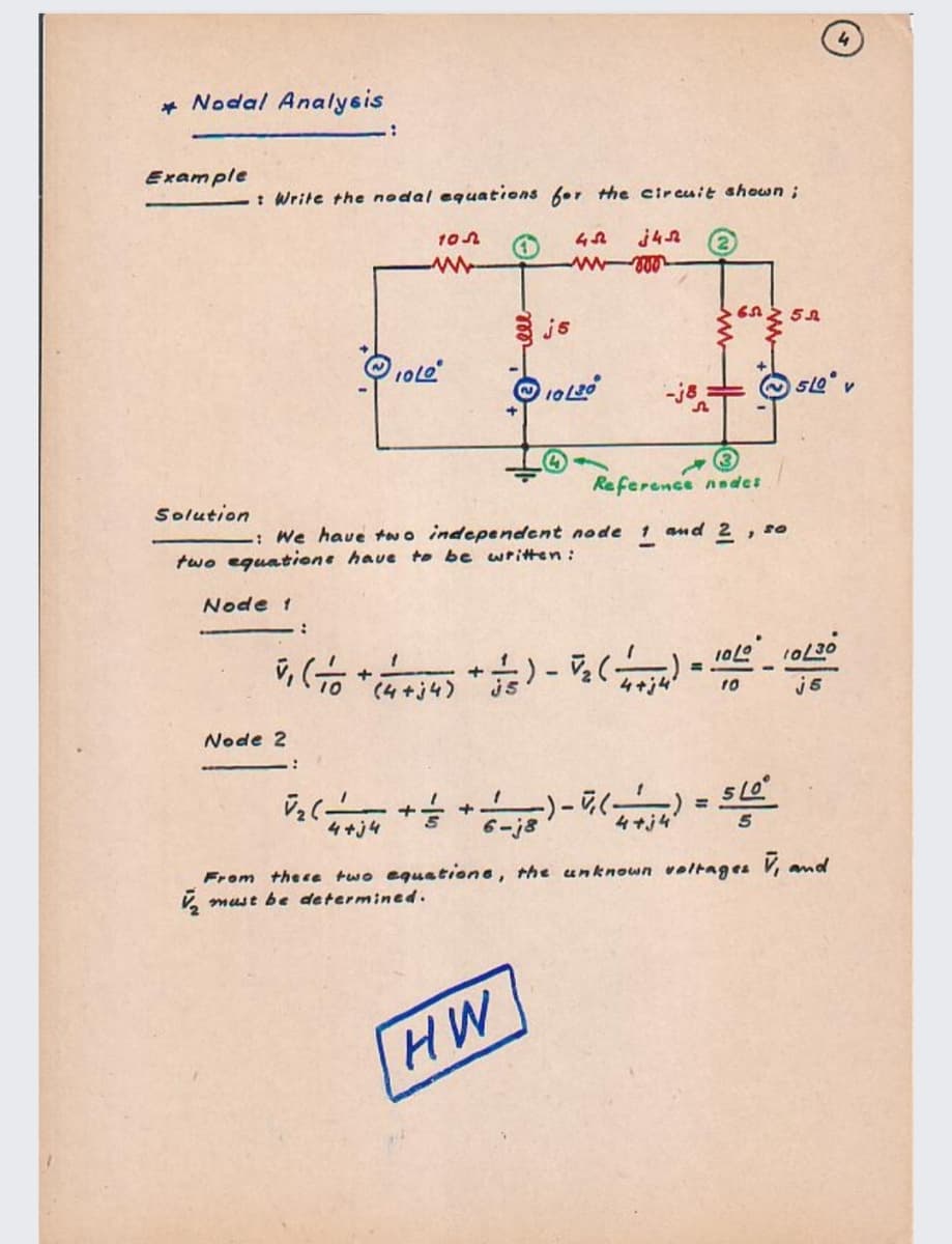
Transcribed Image Text:* Nodal Analysis
Example
: Write the nodal equations for the circuit shown;
102
3 js
Reference nades
Solution
: We have two independent node 1 and 2 , so
two eguatione have to be written :
Node 1
+
(4+j4)
is
4+j4
j5
10
Node 2
+
%3D
4+j4
6-j8
4+j4
From thece two equetione, the unknown voltages V, amd
V, must be determined.
HW
Expert Solution
This question has been solved!
Explore an expertly crafted, step-by-step solution for a thorough understanding of key concepts.

Step by step
Solved in 3 steps with 3 images

Knowledge Booster


Learn more about
Need a deep-dive on the concept behind this application? Look no further. Learn more about this topic, electrical-engineering and related others by exploring similar questions and additional content below.Recommended textbooks for you
Power System Analysis and Design (MindTap Course …
Electrical Engineering
ISBN:
9781305632134
Author:
J. Duncan Glover, Thomas Overbye, Mulukutla S. Sarma
Publisher:
Cengage Learning
Power System Analysis and Design (MindTap Course …
Electrical Engineering
ISBN:
9781305632134
Author:
J. Duncan Glover, Thomas Overbye, Mulukutla S. Sarma
Publisher:
Cengage Learning