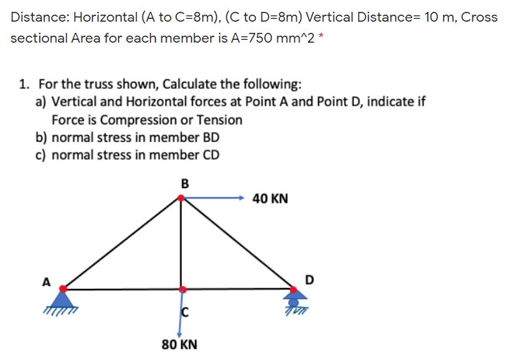
or the truss shown, Calculate the fol Vertical and Horizontal forces at Po Force is Compression or Tension normal stress in member BD normal stress in member CD B.


Q: Consider the element as compression showing in fig. and calculate the effort compression, if the…
A:
Q: The cantilever truss in the figure is hinged at D and E. Find the force in member BC.
A: Given:- Cantilever truss Hinged At D and E To find:- Force at member BC
Q: Determine the force in each member of the truss loaded as shown below. Indicate whether the members…
A:
Q: The cantilever truss in the figure is hinged at D and E. Find the force in member CE.
A:
Q: The truss shown is supported on roller at B and a hinge at F. Find the reactions at B and F. Find…
A:
Q: For the system below, find the maximum stress for the member ECD due to the combined effect of axial…
A:
Q: a ball and socket joint at A and supported by two cables at B. A force P is applied at B where P =…
A:
Q: Q.2) For the truss shown in figure below, determine the forces in BI,Cf, fg lo00
A: Note:As per our guidelines we are supposed to answer only one question. Kindly repost other…
Q: Q1. For the figure shown below, the rigid platform has negligible mass and rests on two steel bars,…
A:
Q: A shelf is being designed to hold crates having a total mass of 1840 kg. Two support rods like that…
A:
Q: PJ-1. In cach case, draw a free-body diagram of the ring at A and identify each force.
A: The expression for the angle made by the tension force in cable AB with the horizontal can be…
Q: In the frame in the figure, AC are horizontal elements and BE are vertical elements. Calculate the…
A: Given-
Q: Q2. As shown in figure, the allowable stress for tension is 200 MPa and the allowable stress for…
A:
Q: Truss below show supports a movable gantry. The beam has a uniform weight of 500 N/m. If x = 3 m and…
A: Given: W = 500 N/m x = 3 m P = 5000 N
Q: 4. The cross sectional area of each member of the truss is 1.6 in?. Calculate the stresses in…
A: GIVEN DATA - A PLANE TRUSS GIVEN WITH AREA 1.6in2 WE HAVE TO FIND STRESS IN GIVEN MEMBER
Q: Find the forces in parts AB, All, ED and EF in the Truss as shown in the figure and specify whether…
A:
Q: For the structure shown in Figure, Compute the forces in all pines.
A:
Q: The force in the truss AB
A: Given data; Trusses support load of =100 NLength of each truss is=1.0Cross-sectional area=200…
Q: 4. Before the 400-kN load is applied, the rigid each of cross-sectional area 1400 mm2, as shown in…
A:
Q: shown in figure, determine: Pif the forces in member (Compression). A. at A and G. members BC, and…
A: Consider Joint Method For support reaction ∑MA = 0 (Positive)(-4 ×2)- ( 5 × 4) - (8 × 8) - (6 ×…
Q: Figure Q1 shows bar ABCD attached to collars B and C which may move freely on its longitudinal axis.…
A:
Q: 2- Find the largest clamping force that can be applied by the cast iron C-clamp if the allowable…
A:
Q: Find the tension of the cord that extends from point C to D and compute for stress experienced by…
A:
Q: shown below, Calculate the support reactions at A and C Calculate the internal force at
A:
Q: A car weighing 130 kN when fully loadedis pulled slowly up a steep inclined track by asteel cable…
A:
Q: Calculate the forces in members BE and BD of the loaded truss. The forces are positive if in…
A:
Q: Calculate the forces in members AC, AD, and DE for the loaded truss. Restraining link BC is…
A:
Q: Given the beam and the external loading shown below, if L = 15 m, w1 = 510 N/m and w2 = 1,600 N/m,…
A:
Q: Calculate the forces in members BE and BD of the loaded truss. The forces are positive if in…
A:
Q: Ok A 30 k 20 k 20 k 20 k 30 k - 30 ft - – 30 fR 30 R 30 ft –
A:
Q: Calculate the forces in members BE and BD of the loaded truss. The forces are positive if in…
A:
Q: Calculate the forces in members AC, AD, and DE for the loaded truss. Restraining link BC is…
A:
Q: For the tension member shown, compute the tensile design strength.
A: In the Image problem was given that Numerical Value is assumed to be 6' .
Q: The cantilever truss in the figure is hinged at D and E. Find the force in member AB.
A:
Q: Q3: For the structure shown in Figure, Compute the forces in all pines. 50 Ib 80 Ib 6 ft (20 Degree)
A:
Q: The cantilever truss shown in the figure is hinged at D and E. Determine the force in each member. A
A:
Q: Q3 Find the reactions in supports 40N/m 4m إضافة ملف
A: Find the reaction at fixed support
Q: Calculate the forces in members AC, AD, and DE for the loaded truss. Restraining link BC is…
A:
Q: Determine all forces acting on member DEF of the frame shown in Figure below:-
A: To determine the force in the member DEF
Q: Find the tension of the cord that extends from point C to D and compute for stress experienced by…
A:
Q: As shown in Fig. 4, a steel frame with Young's modulus E-203 GPa and Poisson's rat v-0.3 is…
A: GivenE=203GPaν=0.3Ro=25cm=0.25mRi=15cm=0.15mt=5cm=0.05m
Q: Calculate the stress in members BC, BD and CD of the trusses shown if the cross- sectional area of…
A:
Q: Find the force in members AC and BC of the Truss shown below?
A:
Q: For the frame shown below, • Calculate the support reactions at A and C Calculate the internal force…
A: Given data Given force system
Q: For the system below, find the maximum stress for the member ECD due to the combined effect of axial…
A:
Q: 3. For the truss shown below, find the internal force of all members using method of sections. 120…
A: In three force members joint with no external load, when the two members are collinear, the third…
Q: 150 Ib/ft B 6 ft D 6 ft 12 ft -8 ft
A:
Q: For a force of 1.25 kN. compute the maximum stress at the fillet under the shoulder.
A: GIven: D=9 mm d=6 mm r=0.5 mm F=1.25 kN TO determine: Maximum stress at fillet
Q: For the pinned frame in the figure, calculate the pin forces acting at point B, on member BD…
A:
Q: Compute the reactions and calculate the force in members CF. Calculate the force member AD.
A: The diagram is: Using the Pythagoras theorem in triangle AOD,
SIMPLE STRAIN
Distance: Horizontal (A to C=8m), (C to D=8m) Vertical Distance= 10 m, Cross sectional Area for each member is A=750 mm^2 *

Step by step
Solved in 2 steps with 2 images

- Continuous cable A DB runs over a small friction less pulley al D to support beam OABC, which is part of an entrance canopy for a building (see figure}. The canopy segment has a weight W = 1700 lb that acts as a concentrated load in the middle of segment AB. (a) What is the maximum permissible value of load P at C if the allowable force in the cable is 4200 lb? (b) If P = 2300 lb, what is the required diameter of pins A, B, and D? Assume that the pins are in double shear and the allowable shear stress in the pins is 10 ksi.During construction of a highway bridge, the main girders are cantilevered outward from one pier toward the next (see figure). Each girder has a cantilever length of 48 m and an I-shaped cross section with dimensions shown in the figure. The load on each girder (during construction) is assumed to be 9,5 kN/m, which includes the weight of the girder. Determine the maximum bending stress in a girder due to this load.A large precast concrete panel for a warehouse is raised using two sets of cables at two lift lines, as shown in the figure part a. Cable 1 has a length L1 = 22 Ft, cable 2 has a length L2= 10 ft, and the distance along the panel between lift points Band D is d = 14 ft (see figure part b). The total weight of the panel is W = 85 kips. Assuming the cable lift Forces F at each lift line are about equal, use the simplified model of one half of the panel in figure part b to perform your analysis for the lift position shown. Find the required cross-sectional area AC of the cable if its breaking stress is 91 ksi and a factor of safety of 4 with respect to failure is desired.
- A single steel strut AB with a diameter (a) Find the strut force Fs and average normal stress ds= 8 mm supports the vehicle engine hood of a in the strut. mass 20 kg that pivots about hinges at C and D (see (b) Find the average shear stress t aver in the bolt at A,figure parts a and b). The strut is bent into a loop at (C) Find the average bearing stress bon the bolt at A. its end and then attached to a bolt at A with a diameter db= 10 mm. Strut AB lies in a vertical plane.A sign of weight W is supported at its base by four bolls anchored in a concrete footing. Wind pressure P acts normal to the surface of the sign; the resultant of the uniform wind pressure is force fat the center of pressure (C.P). The wind force is assumed to create equal shear forces F/4 in the y direction at each boll (see figure parts a and c). The overturning effect of the wind force also causes an uplift force R at bolts A and C and a downward force (— R) al bolts B and D (see figure part b). The resulting effects of the wind and the associated ultimate stresses for each stress condition are normal stress in each boll (h — 60 ksi); shear through the base plate (th = 17 ksi); horizontal shear and bearing on each bolt ( tfur = 25 ksi and cr^ = 75 ksi): and bearing on the bottom washer at B (or D) (abor = 50 ksi).A seesaw weighing 3 lb/ft of length is occupied by two children, each weighing 90 lb (see figure). The center of gravity of each child is 8 ft from the fulcrum. The board is 19 ft long, 8 in. wide, and 1.5 in. thick. What is the maximum bending stress in the board?
- A tie-down on the deck of a sailboat consists of a bent bar boiled at both ends, as shown in the figure. The diameter dBof the bar is 1/4 in., the diameter D Wof the washers is 7/8 in., and the thickness is of the fiberglass deck is 3/8 in. If the allowable shear stress in the fiberglass is 300 psi, and the allowable bearing pressure between the washer and the fiberglass is 550 psi, what is the allowable load P allowon the tie-down?A palm tree weighing 1000 lb is inclined at an angle of 60º (see figure). The weight of the tree may be resolved into two resultant forces: a force P1= 900 lb acting at a point 12 ft from the base and a force P2= 100 lb acting at the top of the tree, which is 30 ft long. The diameter at the base of the tree is 14 in. Calculate the maximum tensile and compressive stresses et, and ec, respectively, at the base of the tree due to its weight.A retaining wall (Fig. a) is constructed using steel W-shape columns and concrete panel infill (Fig, b). Each column is subjected to lateral soil pressure with peak intensity q0(Figs, b and c). The tensile and compressive strength of the beam is 600 MPa. Select the most economical W 360 section from Table F-l(b) based on safety factor of 3.0.
- A plane truss is subjected to loads 2P and P at joints B and C, respectively, as shown in the figure part a. The truss bars are made of two L 102 X 76 X 6.4 steel angles (see Table F-5(b): cross-sectional area or the two angles, A = 2180 mm2, and figure part b) having an ultimate stress in tension equal to 390 MPa. The angles are connected to a 12-mm-thick gusset plate at C(figure part c) with 16-mm diameter rivets; assume each rivet transfers an equal share of the member force to the gusset plate. The ultimate stresses in shear and bearing for the rivet steel are 190 MPa and 550 MPa, respectively. Determine the allowable load Pallowif a safety factor of 2.5 is desired with respect to the ultimate load that can be carried. Consider tension in the bars, shear in the rivets, bearing between the rivets and gusset plate. Disregard friction between the plates the bars, and also bearing between the rivets and the and the weight of the truss itself.A wood beam AB with a rectangular cross section (4 in. × 6 in.) serving as a roof purlin is simply supported by the top chords of two adjacent roof trusses. The beam is subjected to distributed load q acting in the vertical direction through the centroid of the purlin cross section. The top chords of the trusses have a slope of = 27°. The purlin has length L =75 in. Determine the permissible distributed load q based on the allowable compressive and tensile stress in the beam eall = 2 ksi.A square wood platform is 8 ft × 8 ft in area and rests on masonry walls (see figure). The deck of the platform is constructed of 2-in. nominal thickness tongue-and-groove planks (actual thickness 1.5 in.; sec Appendix CL) supported on two S-ft long beams. The beams have 4 in. × (i in. nominal dimensions (actual dimensions 3.5 in. × 5.5 in.). The planks arc designed to support a uniformly distributed load n ( lb/ft" i acting over the entire top surface of the platform. I be allowable bending stress for the planks is 2400 psi and the allowable shear stress is 100 psi. W ben analyzing the planks, disregard their weights and assume that their reactions are uniformly distributed over the top surfaces of the supporting beams. (a) Determine the allowable platform load Mr. (lb/ft2) based upon the bending stress in the planks. (b) Determine the allowable platform load if-. (lb/ft-) based upon the shear stress in the planks. (c) Which of the preceding values becomes the allowable load alolow on the platform? Hints: Use care in constructing the loading diagram for the planks, noting especially that the reactions are distributed loads instead of concentrated loads. Also, note that the maximum shear forces occur at the inside faces of the supporting beams.