Page 429. Sample Problem 6.2.Solve the problem completely;but this time,placethe three applied forces from2.5 kips, 1 kip and 2.5 kips to the new values 3 kips, 2 kipsand1kip.Keep in mind that this change will result inmany other changes across the board.Discuss all practical issues in your findings
Page 429. Sample Problem 6.2.Solve the problem completely;but this time,placethe three applied forces from2.5 kips, 1 kip and 2.5 kips to the new values 3 kips, 2 kipsand1kip.Keep in mind that this change will result inmany other changes across the board.Discuss all practical issues in your findings

Elements Of Electromagnetics
7th Edition
ISBN:9780190698614
Author:Sadiku, Matthew N. O.
Publisher:Sadiku, Matthew N. O.
ChapterMA: Math Assessment
Section: Chapter Questions
Problem 1.1MA

Related questions

Question
Page 429. Sample Problem 6.2.Solve the problem completely;but this time,placethe three applied forces from2.5 kips, 1 kip and 2.5 kips to the new values 3 kips, 2 kipsand1kip.Keep in mind that this change will result inmany other changes across the board.Discuss all practical issues in your findings
Transcribed Image Text:2.5 kips
с
3 kips
(6)
-2--3--3--2-
3 kips
6 kip-ft
b-3.5 in.
3.5 in.
1 kip
-0.5 kip
I
(1.5)
D
I--4
11.25 in
2.5 kips
Fig. 2 Section of
beam having depth d
05 kip
(-1.5)
7.5 kip-ft
E
Fig. 1 Free-body diagram of beam with
shear and bending moment diagrams.
(-6)
3 kips
6 kip-ft
4 in. x 12 in.
nominal size
Fig. 3 Design cross section.
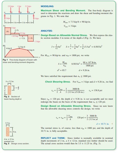
MODELING:
Maximum Shear and Bending Moment. The free-body diagram is
used to determine the reactions and draw the shear and bending-moment dia-
grams in Fig. 1. We note that
ANALYSIS:
**Design Based on Allowable Normal Stress. We first express the elas-
tic section modulus S in terms of the depth d (Fig. 2). We have
-3 kips
1=hd¹ S====bd² = (3.5)d² = 0.5833d²
M
S=
T=
V
For Mx = 90 kip-in. and = 1800 psi, we write
3 V
2 A
M
d² = 85.7
= 7.5 kip-ft = 90 kip-in.
= 3 kips
We have satisfied the requirement that ≤ 1800 psi.
Check Shearing Stress. For Vx = 3 kips and d = 9.26 in., we find
0.5833d²=
==
90 x 10' lb-in.
1800 psi
d = 9.26 in.
3 3000 lb
2 (3.5 in.) (9.26 in.)
3 V
2 A
Since = 120 psi, the depth d= 9.26 in. is not acceptable and we must
redesign the beam on the basis of the requirement that T ≤ 120 psi.
Design Based on Allowable Shearing Stress. Since we now know
that the allowable shearing stress controls the design, we write
T = 138.8 psi
120 psi
3 3000 lb
2 (3.5 in.)d
d = 10.71 in. 4
The normal stress is, of course, less than = 1800 psi, and the depth of
10.71 in. is fully acceptable.
REFLECT and THINK: Since timber is normally available in nominal
depth increments of 2 in., a 4 x 12-in. standard size timber should be used.
The actual cross section would then be 3.5 x 11.25 in. (Fig. 3).
Transcribed Image Text:2.5 kips 1 kip
2.5 kips
2 ft 3 ft 3 ft2
-10 ft-
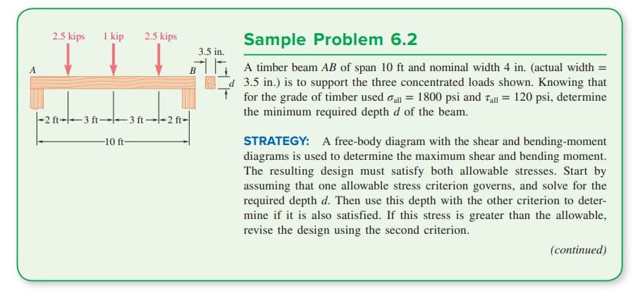
Sample Problem 6.2
3.5 in.
BA timber beam AB of span 10 ft and nominal width 4 in. (actual width =
3.5 in.) is to support the three concentrated loads shown. Knowing that
for the grade of timber used all = 1800 psi and Tall = 120 psi, determine
the minimum required depth d of the beam.
STRATEGY: A free-body diagram with the shear and bending-moment
diagrams is used to determine the maximum shear and bending moment.
The resulting design must satisfy both allowable stresses. Start by
assuming that one allowable stress criterion governs, and solve for the
required depth d. Then use this depth with the other criterion to deter-
mine if it is also satisfied. If this stress is greater than the allowable,
revise the design using the second criterion.
(continued)
Expert Solution
This question has been solved!
Explore an expertly crafted, step-by-step solution for a thorough understanding of key concepts.

This is a popular solution!

Trending now
This is a popular solution!

Step by step
Solved in 4 steps with 4 images

Knowledge Booster


Learn more about
Need a deep-dive on the concept behind this application? Look no further. Learn more about this topic, mechanical-engineering and related others by exploring similar questions and additional content below.Recommended textbooks for you
Elements Of Electromagnetics
Mechanical Engineering
ISBN:
9780190698614
Author:
Sadiku, Matthew N. O.
Publisher:
Oxford University Press

Mechanics of Materials (10th Edition)
Mechanical Engineering
ISBN:
9780134319650
Author:
Russell C. Hibbeler
Publisher:
PEARSON

Thermodynamics: An Engineering Approach
Mechanical Engineering
ISBN:
9781259822674
Author:
Yunus A. Cengel Dr., Michael A. Boles
Publisher:
McGraw-Hill Education
Elements Of Electromagnetics
Mechanical Engineering
ISBN:
9780190698614
Author:
Sadiku, Matthew N. O.
Publisher:
Oxford University Press
Mechanics of Materials (10th Edition)
Mechanical Engineering
ISBN:
9780134319650
Author:
Russell C. Hibbeler
Publisher:
PEARSON
Thermodynamics: An Engineering Approach
Mechanical Engineering
ISBN:
9781259822674
Author:
Yunus A. Cengel Dr., Michael A. Boles
Publisher:
McGraw-Hill Education

Control Systems Engineering
Mechanical Engineering
ISBN:
9781118170519
Author:
Norman S. Nise
Publisher:
WILEY

Mechanics of Materials (MindTap Course List)
Mechanical Engineering
ISBN:
9781337093347
Author:
Barry J. Goodno, James M. Gere
Publisher:
Cengage Learning

Engineering Mechanics: Statics
Mechanical Engineering
ISBN:
9781118807330
Author:
James L. Meriam, L. G. Kraige, J. N. Bolton
Publisher:
WILEY