Part A: Calculation 1- An open-loop DC motor shown in Figure 1. Derive the transfer functions e(s) N(s) and Ea(s) where 0(s) = L(0(t)), N(s) = L(w(t)) and E (s) = L(ea(t)) 2- Find the steady state error in both the position and the speed if the input voltage is 10u(t), and the motor parameters are: La = 10 mH, Ra = 0.5 N, Ja +JL = 3 × Ea(s) %3D %3D 10-4 N.m.sec? rad , Da = 3 x 10⁻³ N.m.sec/rad and K = Kp = K = 0.1 N. m/A 3- If the motor is subjected to a step torque disturbance of amplitude 0.3, calculate the steady state speed in this case.
Part A: Calculation 1- An open-loop DC motor shown in Figure 1. Derive the transfer functions e(s) N(s) and Ea(s) where 0(s) = L(0(t)), N(s) = L(w(t)) and E (s) = L(ea(t)) 2- Find the steady state error in both the position and the speed if the input voltage is 10u(t), and the motor parameters are: La = 10 mH, Ra = 0.5 N, Ja +JL = 3 × Ea(s) %3D %3D 10-4 N.m.sec? rad , Da = 3 x 10⁻³ N.m.sec/rad and K = Kp = K = 0.1 N. m/A 3- If the motor is subjected to a step torque disturbance of amplitude 0.3, calculate the steady state speed in this case.

Introductory Circuit Analysis (13th Edition)
13th Edition
ISBN:9780133923605
Author:Robert L. Boylestad
Publisher:Robert L. Boylestad
Chapter1: Introduction
Section: Chapter Questions
Problem 1P: Visit your local library (at school or home) and describe the extent to which it provides literature...

Related questions
Question
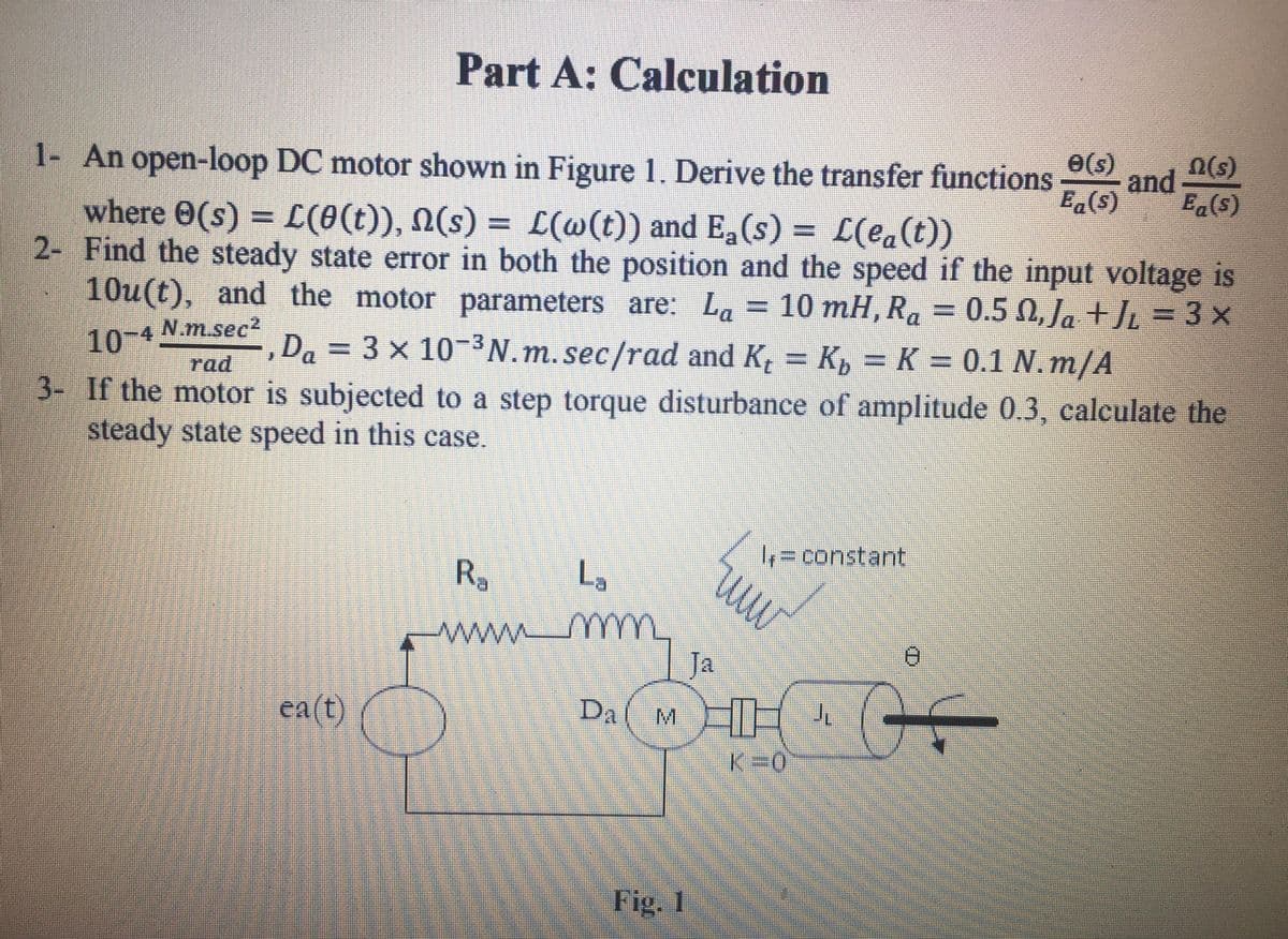
Transcribed Image Text:Part A: Calculation
1- An open-loop DC motor shown in Figure 1. Derive the transfer functions
e(s)
and
E.(s)
n(s)
where 0(s) = L(0(t)), N(s) = L(@(t)) and Ea(s) = L(ea(t))
2- Find the steady state error in both the position and the speed if the input voltage is
10u(t), and the motor parameters are: La = 10 mH, Ra = 0.5 0, Ja +JL = 3 x
%3D
10-4
N.m.sec²
Da = 3 x 10-N.m. sec/rad and K, = K, = K = 0.1 N.m/A
%3D
rad
3- If the motor is subjected to a step torque disturbance of amplitude 0.3, calculate the
steady state speed in this case.
%3Dconstant
R.
L,
mm
ww.
Ja
ea(t)
HH
DA
M.
K=0
Fig. 1
Expert Solution
This question has been solved!
Explore an expertly crafted, step-by-step solution for a thorough understanding of key concepts.

This is a popular solution!

Trending now
This is a popular solution!

Step by step
Solved in 2 steps

Knowledge Booster


Learn more about
Need a deep-dive on the concept behind this application? Look no further. Learn more about this topic, electrical-engineering and related others by exploring similar questions and additional content below.Recommended textbooks for you
Introductory Circuit Analysis (13th Edition)
Electrical Engineering
ISBN:
9780133923605
Author:
Robert L. Boylestad
Publisher:
PEARSON

Delmar's Standard Textbook Of Electricity
Electrical Engineering
ISBN:
9781337900348
Author:
Stephen L. Herman
Publisher:
Cengage Learning

Programmable Logic Controllers
Electrical Engineering
ISBN:
9780073373843
Author:
Frank D. Petruzella
Publisher:
McGraw-Hill Education
Introductory Circuit Analysis (13th Edition)
Electrical Engineering
ISBN:
9780133923605
Author:
Robert L. Boylestad
Publisher:
PEARSON
Delmar's Standard Textbook Of Electricity
Electrical Engineering
ISBN:
9781337900348
Author:
Stephen L. Herman
Publisher:
Cengage Learning
Programmable Logic Controllers
Electrical Engineering
ISBN:
9780073373843
Author:
Frank D. Petruzella
Publisher:
McGraw-Hill Education

Fundamentals of Electric Circuits
Electrical Engineering
ISBN:
9780078028229
Author:
Charles K Alexander, Matthew Sadiku
Publisher:
McGraw-Hill Education

Electric Circuits. (11th Edition)
Electrical Engineering
ISBN:
9780134746968
Author:
James W. Nilsson, Susan Riedel
Publisher:
PEARSON

Engineering Electromagnetics
Electrical Engineering
ISBN:
9780078028151
Author:
Hayt, William H. (william Hart), Jr, BUCK, John A.
Publisher:
Mcgraw-hill Education,