Part3: Resistors connected in a combination of series and parallel The circuit shown below was generated on MapleSIM 2019 Voltmeler 1 Voltmeter 2 Ammeter 2 wwo RI-250hms R2=500hms Ammeter 3 R3=75Ohms Voltmeter 3 Ammeter Total t- 6V The simulated data is shown below, currents are in Amperes and voltages in Volts Analysis Winduw: Simulation Remults Simulation Results RProbe Plots 中。+四A ロ■ Stered Resuts Ammeter 21 Ammeter 34 Ammeter Total i * Latest Resits 0 075 0.055 0.120 0070 0 050- 0115 Verbles MO.045 0.065 0 110 ar 2.
Part3: Resistors connected in a combination of series and parallel The circuit shown below was generated on MapleSIM 2019 Voltmeler 1 Voltmeter 2 Ammeter 2 wwo RI-250hms R2=500hms Ammeter 3 R3=75Ohms Voltmeter 3 Ammeter Total t- 6V The simulated data is shown below, currents are in Amperes and voltages in Volts Analysis Winduw: Simulation Remults Simulation Results RProbe Plots 中。+四A ロ■ Stered Resuts Ammeter 21 Ammeter 34 Ammeter Total i * Latest Resits 0 075 0.055 0.120 0070 0 050- 0115 Verbles MO.045 0.065 0 110 ar 2.

Delmar's Standard Textbook Of Electricity
7th Edition
ISBN:9781337900348
Author:Stephen L. Herman
Publisher:Stephen L. Herman
Chapter29: Dc Generators
Section: Chapter Questions
Problem 1PA: You are working as an electrician in a large steel manufacturing plant, and you are in the process...

Related questions
Question
Already got part 1 and 2 only answer part 3
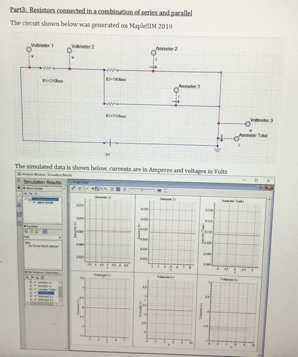
Transcribed Image Text:Part3: Resistors connected in a combination of series and parallel
The circuit shown below was generated on MapleSIM 2019
Voltmeler 1
Voltmeter 2
Ammeter 2
RI=25Ohms
R2=500hms
Ammeter 3
R3=75Ohms
Voltmeter 3
Ammeter Total
to
6V
The simulated data is shown below, currents are in Amperes and voltages in Volts
Analysis Winduw: Simulation Results
- Simulation Results
RProbe Plots
v Stared Resuts
Ammeter 2i
Ammeter 3i
Ammeter Total i
V Latest Reslts
0 075
0.05s-
0 120
0 070-
0.050-
0.115
2.
Vatubles
MO.045
0.065
O110-
Find
Ro 040
0,105
Mar
No Sared Resut Seleced
0.060
0.035
0.100
0.055
0010
3.5 4 45
5 55 6 65
2 34
56 7 S
0.095
4.
4.5
5.5
Plot Windows: Combealion.
Veltmeter 1.v
Valmeten 2v
73
Volmeter 3y
EV Ammeter 2.
Aameter 3.
* Ammeter Tetal
4.5
*votneter 2
v Votmeter 3.
0.5
5.5
2.5
-0.5
24
4.5
10
10
Voltnete 3
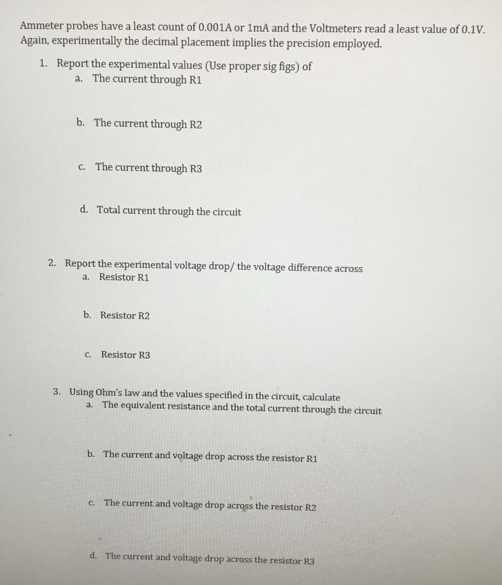
Transcribed Image Text:Ammeter probes have a least count of 0.001A or 1mA and the Voltmeters read a least value of 0.1V.
Again, experimentally the decimal placement implies the precision employed.
1. Report the experimental values (Use proper sig figs) of
a. The current through R1
b. The current through R2
c. The current through R3
d. Total current through the circuit
2. Report the experimental voltage drop/ the voltage difference across
a. Resistor R1
b. Resistor R2
C.
Resistor R3
3. Using Ohm's law and the values specified in the circuit, calculate
a. The equivalent resistance and the total current through the circuit
b. The current and voltage drop across the resistor R1
C.
The current and voltage drop across the resistor R2
d. The current and voltage drop across the resistor R3
Expert Solution
This question has been solved!
Explore an expertly crafted, step-by-step solution for a thorough understanding of key concepts.

This is a popular solution!

Trending now
This is a popular solution!

Step by step
Solved in 2 steps with 2 images

Recommended textbooks for you
Delmar's Standard Textbook Of Electricity
Electrical Engineering
ISBN:
9781337900348
Author:
Stephen L. Herman
Publisher:
Cengage Learning
Delmar's Standard Textbook Of Electricity
Electrical Engineering
ISBN:
9781337900348
Author:
Stephen L. Herman
Publisher:
Cengage Learning