Please I'm begging you i need your help I want you do Graph and table between Shear Stress, τ (GPa) [Axis y] VS Shear Strain, γ [Axis x] (((τ vs Y Graphy)))
Please I'm begging you i need your help I want you do Graph and table between Shear Stress, τ (GPa) [Axis y] VS Shear Strain, γ [Axis x] (((τ vs Y Graphy)))

Elements Of Electromagnetics
7th Edition
ISBN:9780190698614
Author:Sadiku, Matthew N. O.
Publisher:Sadiku, Matthew N. O.
ChapterMA: Math Assessment
Section: Chapter Questions
Problem 1.1MA

Related questions
Question
Please I'm begging you i need your help
I want you do Graph and table between
Shear Stress, τ (GPa) [Axis y]
VS
Shear Strain, γ [Axis x]
(((τ vs Y Graphy)))
Transcribed Image Text:Specimen Length(mm) 140
1.
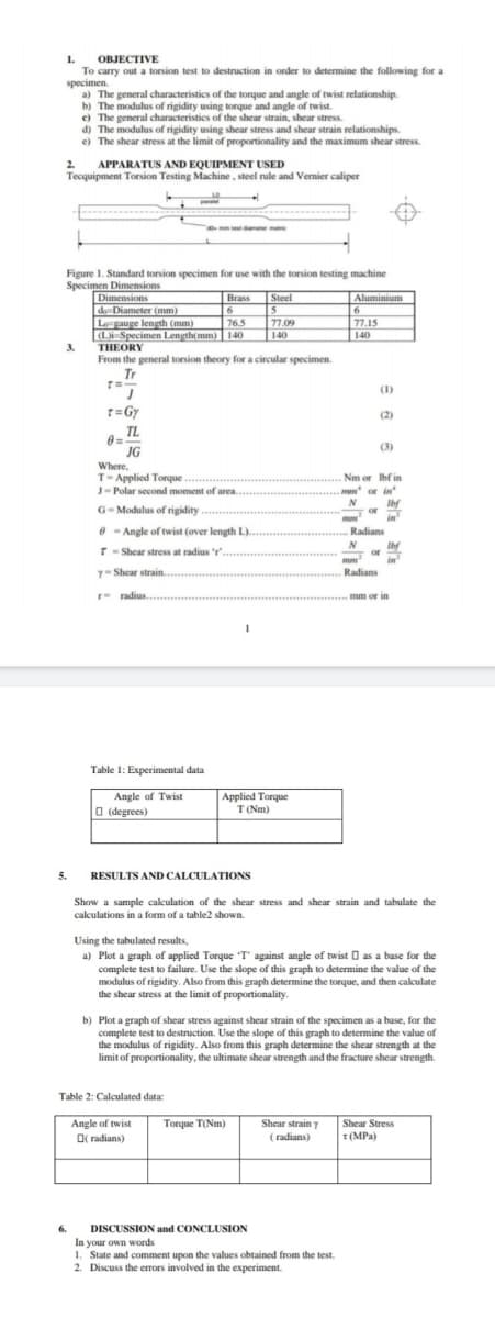
OBJECTIVE
To carry out a torsion test to destruction in order to determine the following for a
specimen.
a) The general characteristics of the torque and angle of twist relationship.
b) The modulus of rigidity using torque and angle of twist
e) The general characteristics of the shear strain, shear stress.
d) The modulus of rigidity using shear stress and shear strain relationships.
e) The shear stress at the limit of proportionality and the maximum shear stress.
2.
APPARATUS AND EQUIPMENT USED
Tecquipment Torsion Testing Machine, steel rule and Vernier caliper
Figure 1. Standard torsion specimen for use with the torsion testing machine
Specimen Dimensions
Dimensions
de=Diameter (mm)
Legauge length (mm)
[(Li-Specimen Length(mm) | 140
THEORY
Aluminium
6
77.15
140
Steel
5
77.09
Brass
76.5
140
3.
From the general torsion theory for a circular specimen.
Tr
1.
r=Gy
(1)
(2)
TL
(3)
JG
Where,
T-Applied Torque ..
J- Polar second moment of area..
Nm or Ibf in
mun or in
N
G-Modulus of rigidity
Ibf
or
in
O - Angle of twist (over length L).
Radians
N
Ibf
or
in
T- Shear stress at radius r'.
.
y- Shear strain.
Radians
r- radius.
mm or in
Table 1: Experimental data
Angle of Twist
O (degrees)
Applied Torque
T(Nm)
5.
RESULTS AND CALCULATIONS
Show a sample calculation of the shear stress and shear strain and tabulate the
calculations in a form of a table2 shown.
Using the tabulated results,
a) Plot a graph of applied Torque "T' against angle of twist O as a base for the
complete test to failure. Use the slope of this graph to determine the value of the
modulus of rigidity. Also from this graph determine the torque, and then calculate
the shear stress at the limit of proportionality.
b) Plot a graph of shear stress against shear strain of the specimen as a base, for the
complete test to destruction. Use the slope of this graph to determine the value of
the modulus of rigidity. Also from this graph determine the shear strength at the
limit of proportionality, the ultimate shear strength and the fracture shear strength.
Table 2: Calculated data:
Shear Stress
T(MPa)
Angle of twist
Torque T(Nm)
Shear strain y
O( radians)
(radians)
6.
DISCUSSION and CONCLUSION
In your own words
1. State and comment upon the values obtained from the test.
2. Discuss the errors involved in the experiment.
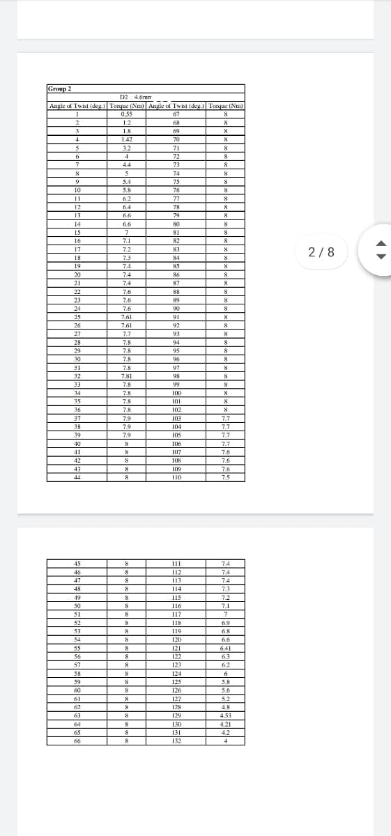
Transcribed Image Text:Group 2
D2 4.6mm
Angle of Twist (deg.) Torque (Nm) Angle of Twist (deg.) Torque (Nm)
0.55
1.2
67
68
8
3.
1.8
69
8
4
1.42
70
3.2
71
4
72
73
8
7
4.4
8
8
74
9
5.4
75
8
10
5.8
76
8
6.2
77
8
12
6.4
78
8
13
6.6
79
14
6.6
80
8
15
7
81
8
16
7.1
82
8
17
7.2
83
8
2/8
18
7.3
84
8
19
7.4
85
8
20
7.4
86
8
21
74
87
8
22
7.6
88
23
7.6
89
24
7.6
90
25
7.61
91
8
26
7.61
92
27
7.7
93
8
28
7.8
94
8
29
7.8
95
96
30
7.8
8.
31
7.8
97
32
7.81
98
33
7.8
99
8
34
7.8
100
35
7.8
101
36
7.8
102
8
37
7.9
103
7.7
38
7.9
104
7.7
39
7.9
105
7.7
40
8
106
7.7
41
107
7.6
42
8
108
7.6
43
8
109
7.6
44
8
110
7.5
45
111
7.4
46
8
112
113
74
74
47
8.
48
8.
114
7.3
49
115
7.2
50
8
116
7.1
51
8
117
52
118
6.9
53
119
6.8
54
120
6.6
55
121
6.41
56
8
122
63
57
8
123
62
58
8
124
6
59
125
5.8
60
126
5.6
61
127
5.2
62
128
4.8
63
129
4.53
64
8
130
4.21
65
8
131
4.2
8
132
4
Expert Solution
This question has been solved!
Explore an expertly crafted, step-by-step solution for a thorough understanding of key concepts.

Step by step
Solved in 3 steps with 2 images

Knowledge Booster


Learn more about
Need a deep-dive on the concept behind this application? Look no further. Learn more about this topic, mechanical-engineering and related others by exploring similar questions and additional content below.Recommended textbooks for you
Elements Of Electromagnetics
Mechanical Engineering
ISBN:
9780190698614
Author:
Sadiku, Matthew N. O.
Publisher:
Oxford University Press

Mechanics of Materials (10th Edition)
Mechanical Engineering
ISBN:
9780134319650
Author:
Russell C. Hibbeler
Publisher:
PEARSON

Thermodynamics: An Engineering Approach
Mechanical Engineering
ISBN:
9781259822674
Author:
Yunus A. Cengel Dr., Michael A. Boles
Publisher:
McGraw-Hill Education
Elements Of Electromagnetics
Mechanical Engineering
ISBN:
9780190698614
Author:
Sadiku, Matthew N. O.
Publisher:
Oxford University Press
Mechanics of Materials (10th Edition)
Mechanical Engineering
ISBN:
9780134319650
Author:
Russell C. Hibbeler
Publisher:
PEARSON
Thermodynamics: An Engineering Approach
Mechanical Engineering
ISBN:
9781259822674
Author:
Yunus A. Cengel Dr., Michael A. Boles
Publisher:
McGraw-Hill Education

Control Systems Engineering
Mechanical Engineering
ISBN:
9781118170519
Author:
Norman S. Nise
Publisher:
WILEY

Mechanics of Materials (MindTap Course List)
Mechanical Engineering
ISBN:
9781337093347
Author:
Barry J. Goodno, James M. Gere
Publisher:
Cengage Learning

Engineering Mechanics: Statics
Mechanical Engineering
ISBN:
9781118807330
Author:
James L. Meriam, L. G. Kraige, J. N. Bolton
Publisher:
WILEY