Problem 1 : Given the following structure, for which the torque is applied at point A,B, C, D and E, respectively as, Ta = 12 kN.m , Tg = 6 kN.m, Tc = 5 kN.m, Tp = -20 kN.m, and TE = -3 kN.m. The lengths of the shaft are given as LaB = 0.3 m, LBc = 0.6 m, Lcd = 0.9 m, and LpE = 0.4 m. %3D %3D %3D %3D %3D
Problem 1 : Given the following structure, for which the torque is applied at point A,B, C, D and E, respectively as, Ta = 12 kN.m , Tg = 6 kN.m, Tc = 5 kN.m, Tp = -20 kN.m, and TE = -3 kN.m. The lengths of the shaft are given as LaB = 0.3 m, LBc = 0.6 m, Lcd = 0.9 m, and LpE = 0.4 m. %3D %3D %3D %3D %3D

Elements Of Electromagnetics
7th Edition
ISBN:9780190698614
Author:Sadiku, Matthew N. O.
Publisher:Sadiku, Matthew N. O.
ChapterMA: Math Assessment
Section: Chapter Questions
Problem 1.1MA

Related questions
Question
Please answer for that now
Transcribed Image Text:08:44 MP matic cross section, yield strength, the stress intensíN am
and fracture strength.
2) Describe (in your own words and in a clear way) th Poisson'sffect,
ENGINEERING MEC...
3) Draw the chart showing the main types of stresses and strains.(Bonus :
draw some illustrations for each stress)
4) Body forces are developed when one body exerts a force on another body
without direct physical contact. T/F. Justify.
5) Britility nature is when the material show a plastic deformation. T/F.
Justify.
6) Generally, bending happens when a bending moment is applied to a beam
without the simultaneous presence of axial, shear or torsional forces. T/F.
Justify.
7) The neutral axis passes through the center of mass of the stru
T/F . Justify.
yze
2/4
8) The first moment of area is defined physically as mass measure of the
spatial distribution of a shape in its relation to an axis. T/F. Justify.
9) Give real life applications of torque, pure bending, and tension stresses.
10) Express the polar moment of inertia, in terms of the second moments of
inertia. When do we use the parallel-axis theorem ? (Show all the details.)
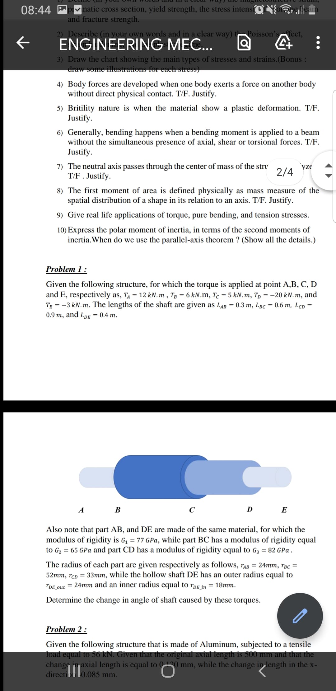
Problem 1 :
Given the following structure, for which the torque is applied at point A,B, C, D
and E, respectively as, T = 12 kN.m , Tg = 6 kN.m, Tc = 5 kN.m, Tp = -20 kN.m, and
TE = -3 kN.m. The lengths of the shaft are given as LaB = 0.3 m, LBc = 0.6 m, LcD =
0.9 m, and LpE = 0.4 m.
A B
C
D
E
Also note that part AB, and DE are made of the same material, for which the
modulus of rigidity is G, = 77 GPa, while part BC has a modulus of rigidity equal
to G2 = 65 GPa and part CD has a modulus of rigidity equal to G3 = 82 GPa .
The radius of each part are given respectively as follows, raB = 24mm, rBc =
52mm, rcD = 33mm, while the hollow shaft DE has an outer radius equal to
rdE out = 24mm and an inner radius equal to rdE in = 18mm.
Determine the change in angle of shaft caused by these torques.
Problem 2 :
Given the following structure that is made of Aluminum, subjected to a tensile
load equal to 56 kN. Given that the original axial length is 500 mm and that the
change in axial length is equal to 0130 mm, while the change inlength in the x-
directibu 0.085 mm.
Expert Solution
This question has been solved!
Explore an expertly crafted, step-by-step solution for a thorough understanding of key concepts.

Step by step
Solved in 2 steps

Knowledge Booster


Learn more about
Need a deep-dive on the concept behind this application? Look no further. Learn more about this topic, mechanical-engineering and related others by exploring similar questions and additional content below.Recommended textbooks for you
Elements Of Electromagnetics
Mechanical Engineering
ISBN:
9780190698614
Author:
Sadiku, Matthew N. O.
Publisher:
Oxford University Press

Mechanics of Materials (10th Edition)
Mechanical Engineering
ISBN:
9780134319650
Author:
Russell C. Hibbeler
Publisher:
PEARSON

Thermodynamics: An Engineering Approach
Mechanical Engineering
ISBN:
9781259822674
Author:
Yunus A. Cengel Dr., Michael A. Boles
Publisher:
McGraw-Hill Education
Elements Of Electromagnetics
Mechanical Engineering
ISBN:
9780190698614
Author:
Sadiku, Matthew N. O.
Publisher:
Oxford University Press
Mechanics of Materials (10th Edition)
Mechanical Engineering
ISBN:
9780134319650
Author:
Russell C. Hibbeler
Publisher:
PEARSON
Thermodynamics: An Engineering Approach
Mechanical Engineering
ISBN:
9781259822674
Author:
Yunus A. Cengel Dr., Michael A. Boles
Publisher:
McGraw-Hill Education

Control Systems Engineering
Mechanical Engineering
ISBN:
9781118170519
Author:
Norman S. Nise
Publisher:
WILEY

Mechanics of Materials (MindTap Course List)
Mechanical Engineering
ISBN:
9781337093347
Author:
Barry J. Goodno, James M. Gere
Publisher:
Cengage Learning

Engineering Mechanics: Statics
Mechanical Engineering
ISBN:
9781118807330
Author:
James L. Meriam, L. G. Kraige, J. N. Bolton
Publisher:
WILEY