Problem 2: Consider controlling the Omron G5LE-1 5VDC power relay, shown below, using in the following circuit. A relay has windings that when energized cause a magnetic field, which mechanically closes the contact side of the relay, so it acts as an electronically controlled switch. One benefit of a relay is that the switch on the contact side is electrically isolated from the coil on the control side of the relay. This advantage of electrical isolation comes at a cost. Relays do not switch states quickly like transistors. Based on its data sheet, the Omron G5LE-1 5VDC has a coil resistance of 632 (at DC, consider the coil side of the relay as a resistor). Select the base resistance to ensure the P2N222A BJT is deep into saturation when the relay is energized (meaning current is flowing through its windings). onerate the Omron G5LE-1 at up to 130% of its rated voltage of 5VDC in its
Problem 2: Consider controlling the Omron G5LE-1 5VDC power relay, shown below, using in the following circuit. A relay has windings that when energized cause a magnetic field, which mechanically closes the contact side of the relay, so it acts as an electronically controlled switch. One benefit of a relay is that the switch on the contact side is electrically isolated from the coil on the control side of the relay. This advantage of electrical isolation comes at a cost. Relays do not switch states quickly like transistors. Based on its data sheet, the Omron G5LE-1 5VDC has a coil resistance of 632 (at DC, consider the coil side of the relay as a resistor). Select the base resistance to ensure the P2N222A BJT is deep into saturation when the relay is energized (meaning current is flowing through its windings). onerate the Omron G5LE-1 at up to 130% of its rated voltage of 5VDC in its

Chapter19: Special-purpose Outlets-water Pump, Water Heater
Section19.1: Water Pump And Branch Circuit
Problem 21R: Fill in the data for a 16-ampere electric motor, single-phase, no Code letters. a. Branch-circuit...

Related questions

Question
Please answer the question below. Thank you so much!!
Transcribed Image Text:Answer
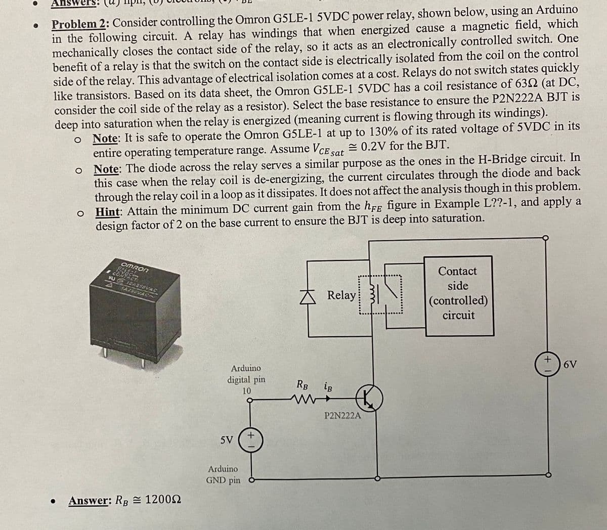
Problem 2: Consider controlling the Omron G5LE-1 5VDC power relay, shown below, using an Arduino
in the following circuit. A relay has windings that when energized cause a magnetic field, which
mechanically closes the contact side of the relay, so it acts as an electronically controlled switch. One
benefit of a relay is that the switch on the contact side is electrically isolated from the coil on the control
side of the relay. This advantage of electrical isolation comes at a cost. Relays do not switch states quickly
like transistors. Based on its data sheet, the Omron G5LE-1 5VDC has a coil resistance of 632 (at DC,
consider the coil side of the relay as a resistor). Select the base resistance to ensure the P2N222A BJT is
deep into saturation when the relay is energized (meaning current is flowing through its windings).
o Note: It is safe to operate the Omron G5LE-1 at up to 130% of its rated voltage of 5VDC in its
= 0.2V for the BJT.
entire operating temperature range. Assume VcE sat
o Note: The diode across the relay serves a similar purpose as the ones in the H-Bridge circuit. In
this case when the relay coil is de-energizing, the current circulates through the diode and back
through the relay coil in a loop as it dissipates. It does not affect the analysis though in this problem.
o Hint: Attain the minimum DC current gain from the hFF figure in Example L??-1, and apply a
design factor of 2 on the base current to ensure the BJT is deep into saturation.
OMRON
Contact
FU E1CA250VAC
side
SA2SDVAC~
Relay 3
(controlled)
circuit
6V
Arduino
digital pin
RB
ig
10
P2N222A
5V
Arduino
GND pin ở
Answer: RB = 12002
Expert Solution
This question has been solved!
Explore an expertly crafted, step-by-step solution for a thorough understanding of key concepts.

Step by step
Solved in 2 steps

Knowledge Booster


Learn more about
Need a deep-dive on the concept behind this application? Look no further. Learn more about this topic, electrical-engineering and related others by exploring similar questions and additional content below.Recommended textbooks for you
EBK ELECTRICAL WIRING RESIDENTIAL
Electrical Engineering
ISBN:
9781337516549
Author:
Simmons
Publisher:
CENGAGE LEARNING - CONSIGNMENT

Power System Analysis and Design (MindTap Course …
Electrical Engineering
ISBN:
9781305632134
Author:
J. Duncan Glover, Thomas Overbye, Mulukutla S. Sarma
Publisher:
Cengage Learning
EBK ELECTRICAL WIRING RESIDENTIAL
Electrical Engineering
ISBN:
9781337516549
Author:
Simmons
Publisher:
CENGAGE LEARNING - CONSIGNMENT
Power System Analysis and Design (MindTap Course …
Electrical Engineering
ISBN:
9781305632134
Author:
J. Duncan Glover, Thomas Overbye, Mulukutla S. Sarma
Publisher:
Cengage Learning