PROBLEM 2 Given is a truss structure: Where: Working shear stress for the rivets is 70 MPa Working bearing stress due to rivets is 140 Mpa Thickness of the member is 5 mm Thickness of the Gusset plate is 6 mm Rivet diameter is 15 mm Determine the no. of rivets to fasten the member BD 50 kN 30 kN com 5 m 4 m 4 m C 4 m 3 m E
PROBLEM 2 Given is a truss structure: Where: Working shear stress for the rivets is 70 MPa Working bearing stress due to rivets is 140 Mpa Thickness of the member is 5 mm Thickness of the Gusset plate is 6 mm Rivet diameter is 15 mm Determine the no. of rivets to fasten the member BD 50 kN 30 kN com 5 m 4 m 4 m C 4 m 3 m E

Mechanics of Materials (MindTap Course List)
9th Edition
ISBN:9781337093347
Author:Barry J. Goodno, James M. Gere
Publisher:Barry J. Goodno, James M. Gere
Chapter1: Tension, Compression, And Shear
Section: Chapter Questions
Problem 1.10.5P: A plane truss has joint loads P, 2P, and 3P at joints D. C, and B. respectively (see figure) where...

Related questions
Question
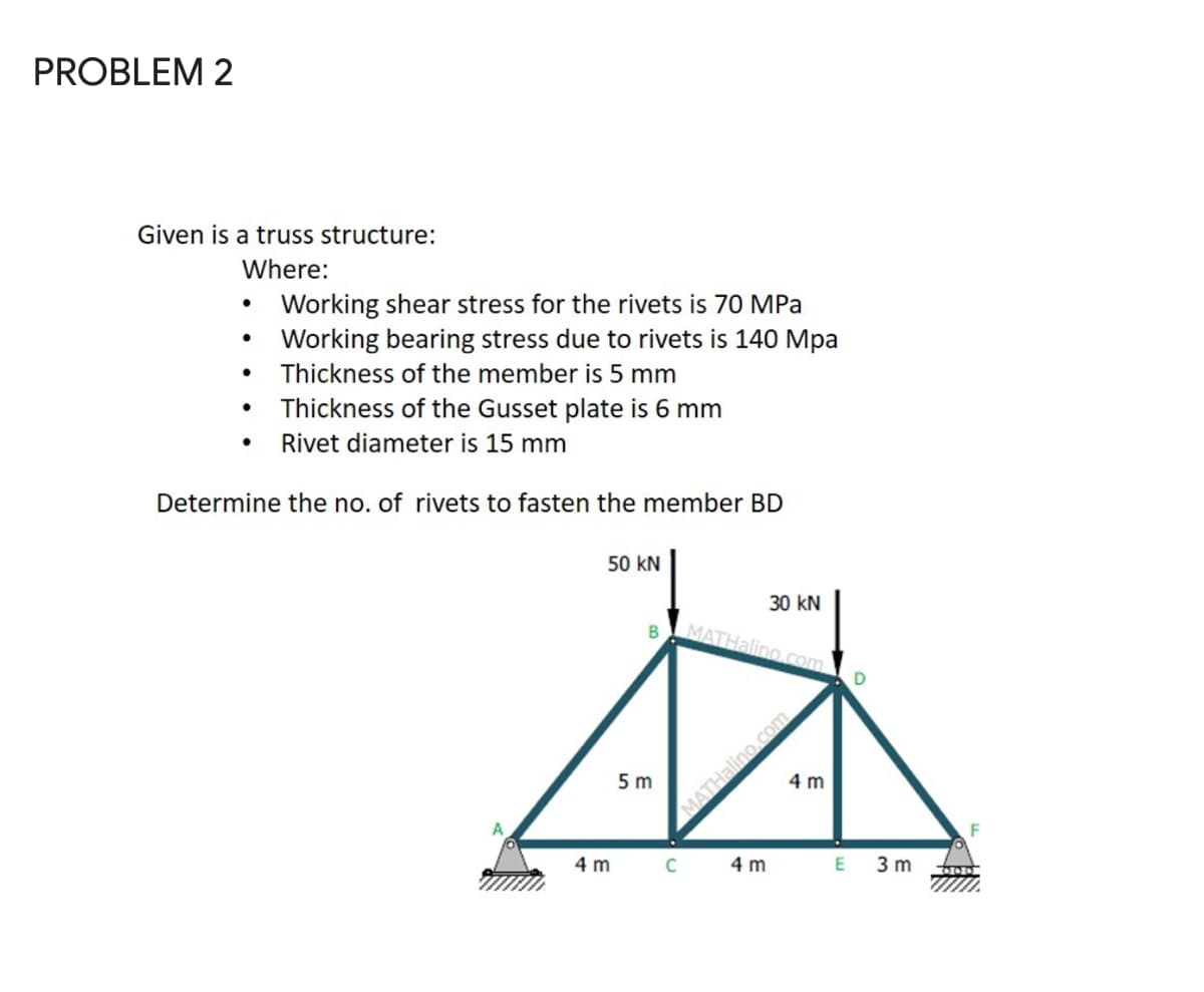
Transcribed Image Text:PROBLEM 2
Given is a truss structure:
Where:
Working shear stress for the rivets is 70 MPa
• Working bearing stress due to rivets is 140 Mpa
Thickness of the member is 5 mm
Thickness of the Gusset plate is 6 mm
Rivet diameter is 15 mm
Determine the no. of rivets to fasten the member BD
50 kN
30 kN
B
MATHalino.com
5 m
4 m
4 m
4 m
3 m
Expert Solution
This question has been solved!
Explore an expertly crafted, step-by-step solution for a thorough understanding of key concepts.

This is a popular solution!

Trending now
This is a popular solution!

Step by step
Solved in 3 steps with 5 images

Knowledge Booster


Learn more about
Need a deep-dive on the concept behind this application? Look no further. Learn more about this topic, mechanical-engineering and related others by exploring similar questions and additional content below.Recommended textbooks for you
Mechanics of Materials (MindTap Course List)
Mechanical Engineering
ISBN:
9781337093347
Author:
Barry J. Goodno, James M. Gere
Publisher:
Cengage Learning
Mechanics of Materials (MindTap Course List)
Mechanical Engineering
ISBN:
9781337093347
Author:
Barry J. Goodno, James M. Gere
Publisher:
Cengage Learning