Problem 4) Consider a separately-excited DC motor with the following parameters: Trated = 10 N-m Nrated = 3700 RPM Kt = 0.5 n-m/A (motor Torque Constant) Kb = 53V/1000RPM (Back-EMF Constant) Ra = 0.37 ohm La = 0.15 mH a) Calculate (by hand) the terminal voltage required to deliver a steady-state torque of 5 N- m at a speed of 1500 rpm. b) Model the motor described above in Simulink with motor inertia, J=0.15, and bearing friction coefficient B=0.05. Apply a step change in armature voltage at t=1sec from 0- 85V. Provide plots (with white backgrounds and axis labels) of armature current and rotor speed in RPM. Run the model until a steady-state is achieved.
Problem 4) Consider a separately-excited DC motor with the following parameters: Trated = 10 N-m Nrated = 3700 RPM Kt = 0.5 n-m/A (motor Torque Constant) Kb = 53V/1000RPM (Back-EMF Constant) Ra = 0.37 ohm La = 0.15 mH a) Calculate (by hand) the terminal voltage required to deliver a steady-state torque of 5 N- m at a speed of 1500 rpm. b) Model the motor described above in Simulink with motor inertia, J=0.15, and bearing friction coefficient B=0.05. Apply a step change in armature voltage at t=1sec from 0- 85V. Provide plots (with white backgrounds and axis labels) of armature current and rotor speed in RPM. Run the model until a steady-state is achieved.

Introductory Circuit Analysis (13th Edition)
13th Edition
ISBN:9780133923605
Author:Robert L. Boylestad
Publisher:Robert L. Boylestad
Chapter1: Introduction
Section: Chapter Questions
Problem 1P: Visit your local library (at school or home) and describe the extent to which it provides literature...

Related questions

Question
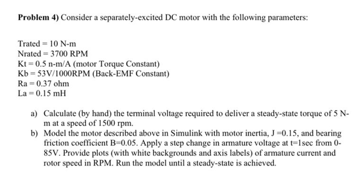
Transcribed Image Text:Problem 4) Consider a separately-excited DC motor with the following parameters:
Trated = 10 N-m
Nrated = 3700 RPM
Kt = 0.5 n-m/A (motor Torque Constant)
Kb = 53V/1000RPM (Back-EMF Constant)
Ra = 0.37 ohm
La = 0.15 mH
a) Calculate (by hand) the terminal voltage required to deliver a steady-state torque of 5 N-
m at a speed of 1500 rpm.
b) Model the motor described above in Simulink with motor inertia, J=0.15, and bearing
friction coefficient B=0.05. Apply a step change in armature voltage at t=1sec from 0-
85V. Provide plots (with white backgrounds and axis labels) of armature current and
rotor speed in RPM. Run the model until a steady-state is achieved.
Expert Solution
This question has been solved!
Explore an expertly crafted, step-by-step solution for a thorough understanding of key concepts.

This is a popular solution!

Trending now
This is a popular solution!

Step by step
Solved in 2 steps with 2 images

Knowledge Booster


Learn more about
Need a deep-dive on the concept behind this application? Look no further. Learn more about this topic, electrical-engineering and related others by exploring similar questions and additional content below.Recommended textbooks for you
Introductory Circuit Analysis (13th Edition)
Electrical Engineering
ISBN:
9780133923605
Author:
Robert L. Boylestad
Publisher:
PEARSON

Delmar's Standard Textbook Of Electricity
Electrical Engineering
ISBN:
9781337900348
Author:
Stephen L. Herman
Publisher:
Cengage Learning

Programmable Logic Controllers
Electrical Engineering
ISBN:
9780073373843
Author:
Frank D. Petruzella
Publisher:
McGraw-Hill Education
Introductory Circuit Analysis (13th Edition)
Electrical Engineering
ISBN:
9780133923605
Author:
Robert L. Boylestad
Publisher:
PEARSON
Delmar's Standard Textbook Of Electricity
Electrical Engineering
ISBN:
9781337900348
Author:
Stephen L. Herman
Publisher:
Cengage Learning
Programmable Logic Controllers
Electrical Engineering
ISBN:
9780073373843
Author:
Frank D. Petruzella
Publisher:
McGraw-Hill Education

Fundamentals of Electric Circuits
Electrical Engineering
ISBN:
9780078028229
Author:
Charles K Alexander, Matthew Sadiku
Publisher:
McGraw-Hill Education

Electric Circuits. (11th Edition)
Electrical Engineering
ISBN:
9780134746968
Author:
James W. Nilsson, Susan Riedel
Publisher:
PEARSON

Engineering Electromagnetics
Electrical Engineering
ISBN:
9780078028151
Author:
Hayt, William H. (william Hart), Jr, BUCK, John A.
Publisher:
Mcgraw-hill Education,