PROBLEM 5/6 Rigid bars AB and BCD are supported by pins A and D and by a steel rod at C. There is a roller E = 200 Gpa A = 300 mm² L = 3.5 m 70 kN connection between the bars at B. 2 m 1.8 m D Compute the vertical displacement of point B caused by the 70 kN load. A 1.5 m 2.5 m
PROBLEM 5/6 Rigid bars AB and BCD are supported by pins A and D and by a steel rod at C. There is a roller E = 200 Gpa A = 300 mm² L = 3.5 m 70 kN connection between the bars at B. 2 m 1.8 m D Compute the vertical displacement of point B caused by the 70 kN load. A 1.5 m 2.5 m

Mechanics of Materials (MindTap Course List)
9th Edition
ISBN:9781337093347
Author:Barry J. Goodno, James M. Gere
Publisher:Barry J. Goodno, James M. Gere
Chapter11: Columns
Section: Chapter Questions
Problem 11.4.14P

Related questions
Question
Transcribed Image Text:PROBLEM 5/6
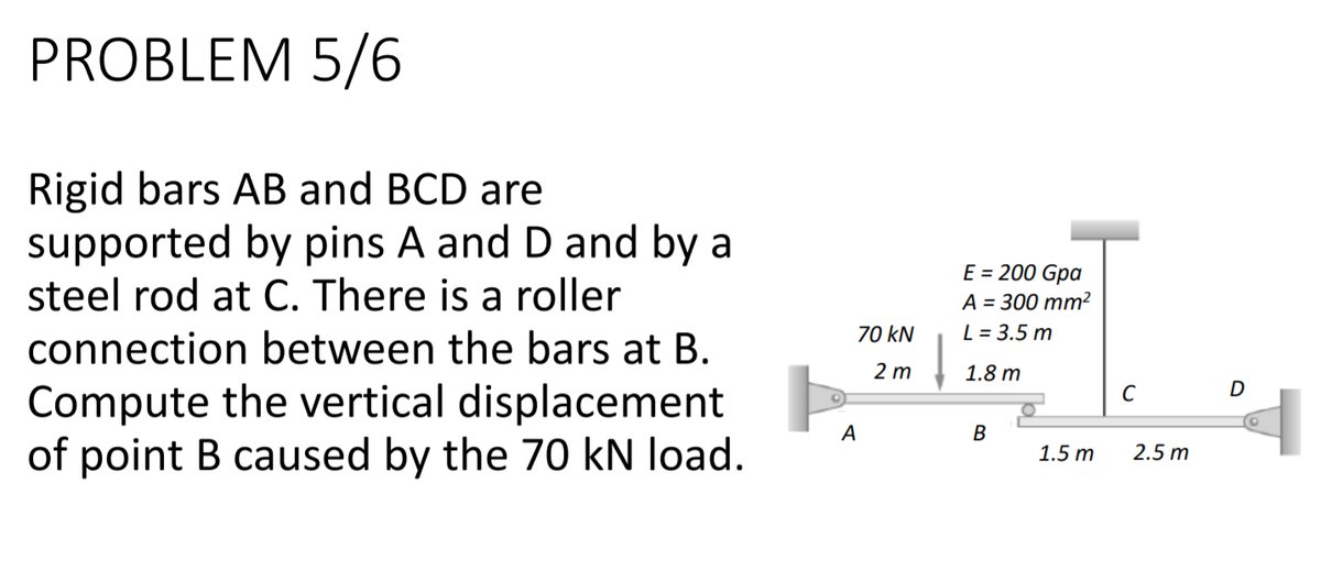
Rigid bars AB and BCD are
supported by pins A and D and by a
steel rod at C. There is a roller
E = 200 Gpa
A = 300 mm²
L = 3.5 m
70 kN
connection between the bars at B.
2 m
1.8 m
D
Compute the vertical displacement
of point B caused by the 70 kN load.
A
1.5 m
2.5 m
Expert Solution
This question has been solved!
Explore an expertly crafted, step-by-step solution for a thorough understanding of key concepts.

Step by step
Solved in 2 steps with 2 images

Recommended textbooks for you
Mechanics of Materials (MindTap Course List)
Mechanical Engineering
ISBN:
9781337093347
Author:
Barry J. Goodno, James M. Gere
Publisher:
Cengage Learning
Mechanics of Materials (MindTap Course List)
Mechanical Engineering
ISBN:
9781337093347
Author:
Barry J. Goodno, James M. Gere
Publisher:
Cengage Learning