PROBLEM 05. Refer to problem SP203. Change P=25 KN up to the left at 30 degrees w/ x-axis, Q=30 KN, W=35 KN, T=18 KN directed to the right.
Q: Sketch the distribution of the shear stress due to torsion in a circular shaft. (simple sketch of…
A: Given : shear stress due to torsion in a circular shaft varies with shaft radius To find : Sketch…
Q: Q1) For the below figure (1), Find the magnitude of force required to rolling the cylinder over the…
A:
Q: Draw the free body diagrams for each part in the figures below:
A: To draw the free body diagram.
Q: Write legibly, provide manual step by step solution, and diagram for below given problem. A 100 mm…
A:
Q: a pin jointed four bar mechanism, s shown in the figure, crank AB = 50 mm and rotate clockwise at…
A:
Q: Problem 1.12: A journal 25 mm in diameter and supported in sliding bearing has maximum end reaction…
A: Given data: d=25 mmW=25 kNPb=5 N/mm2 Need to determine the length of sliding bearing.
Q: Draw a frame diagram to show their arrangement qualitatively, and solve for "T.
A: Solution
Q: 2. For the system shown below, compute the maximum torque it can accommodate if a is 2000mm and b is…
A: Find the maximum torque .
Q: Figure shows an automobile wheel with two common styles of lug wrench being used to tighten the…
A:
Q: 2. Draw the free body diagram of the figure below.
A: Free body diagram is the diagram which shows all the forces acting on a body.
Q: A 6m long solid steel pole is emphasized at 80 MPa when twisting through 6 °. Using G = 83 GPa,…
A: given data Length of pole (L) = 6 m shear stress (τ) = 80 MPa θ = 6o = π180*6=0.1047rad G = 83 GPa…
Q: Define I) torque II) torsional loads b)A solid circular shaft is to transmit 80kw power at…
A: Torque is defined as moment of force acting about an axis which is cabable of producing angular…
Q: The diameter of the pin to be used at the B point in the brake mechanism in the figure is dB = 12 mm…
A:
Q: Problem 2 The landing gear of an aircraft is depicted in Figure below. What are the required pin…
A: Apply the conditions of equilibrium ∑MA=0By×16=-10sin15°×(16+16)By=-5.176 kips…
Q: Problem 2.2 Consider the following load raising system. a) Calculate the power of the motor if the…
A: Given figure To calculate (a)Calculate the power of the motor if the load is to be raised at a…
Q: Which of the folloving equations correctiy describe the bending moment M and torsion Tin section BC…
A:
Q: A solid steel shaft of radius b is to be pressed into a wrought iron hub of outer radius c and…
A: A solid steel shaft of radius b is to be pressed into a wrought iron hub of outer radius c and…
Q: In the figure, bearings B and D from points A and E Tangential forces from the gears in the vertical…
A: Given: The tangential load in vertical direction, Fy = 2100 N The yield strength of material, Sy =…
Q: 24. Find F12 for the cone shown in the figure. Use R = 0.5 m and L, = 1.5 m. Surface A2 has the same…
A:
Q: For the figure shown, use P = 100 kN, L = 300mm, 5 = 100 mm and S2 = 180 mm. Assume the diameter of…
A: Ans: 14. b 15. d 16. a
Q: Problem 6.2. The undeformed and deformed outline of a material element are as shown in the figure…
A:
Q: The non-rotating shaft shown in Fig. E-4.7 is subjected to a load P varying from 4000 N to 12000 N.…
A:
Q: GPa, Modulus of Rigidity = 70 GPa, Ultimate stress = 620 MPa, Compression stress = 240 MPa, Yield…
A:
Q: Consider the case of shafts subjected to bending moment only. Figure Q2 shows a pair of wheels of a…
A: Given:- P=50kN Gauge length= 1.4m Max stress=100MPa k=dido=0.5 To find:- 1) Diameter of axel, d 2)…
Q: A bevel gear is attached to a shaft supported by self-aligning bearings at A and B and is driven by…
A:
Q: shift is subjected to the axial loads shows. If copper has an E=18×10^6Psi and the diameters of each…
A:
Q: wire - 15 mm R Wire clip 3. The figure shows a finger exerciser. It is based on torsion spring. The…
A: A finger exerciser is used to make fingers strong. Force is applied to the handle so that spring…
Q: Q3. A welded steel cylindrical drum made of a 15mm thickness plate has an internal diameter of 1.50…
A:
Q: A shaft of 30 kW 710 r.p.m motor is 40 mm in diameter and is supported in bearings 500 mm apart.…
A: Given: The power of shaft is P=30 kW The revolution of shaft per minute is N=710 rpm The diameter…
Q: Problem 1 : Given the following structure, for which the torque is applied at point A,B, C, D and E,…
A: Given data: Torque values are given as TA = 12 kN-m , TB = 6 kN-m , TC = 5…
Q: Example 3.4. A uniform wheel of 600 mm diameter, weighing 5 kN rests against a rigid tangular block…
A: Diameter=600mm weight of wheel=5kN
Q: PROBLEM 5/6 Rigid bars AB and BCD are supported by pins A and D and by a steel rod at C. There is a…
A:
Q: vator torque tube is made of 24S-T aluminum alloy & has dimensions of 2- by 0.083 in. Find the angle…
A: Given:Dimension: 2 in by 0.083 inζ=10,000 psiL=80 in
Q: A force Q (= 6B kN) is applied through the handle of the rigid steel lever (ABCDE), causing the…
A:
Q: The solid spindle AB has a diameter ds=40mm and is made of a steel with G=110GPa and Tem=120MPa ,…
A:
Q: A solid round bar is to be assembled into a collar by press fitting. The inside radius of the collar…
A: Given Data The inside radius of the collar is: R=50 mm The outer radius is: r=40 mm The facor of…
Q: Figure Q4(B)(a) shows a hollow quarry drill bit in operation. When drilling, it experiences…
A:
Q: A steel shaft is transmitting 50 Hp at 1200 rpm. The nature of load and type o service of the shaft…
A:
Q: Figure Q(1) shows an assembly of an impeller. The shaft (4) is supported by two bearings: the…
A: Suppose the constants X and Y for bearing 2 are 0.56 and 1.5. Suppose the constants X and Y for…
Q: A 13-kN hydraulic press for removing and reinstalling bearings in small-to medium-sized electric…
A: Given Su = 345 Mpa Force = 13 kN Given figure
Q: A 13-kN hydraulic press for removing and reinstalling bearings in small-to medium-sized electric…
A: Draw a diagram showing the centroidal axis and neutral axis in the cross-section. Here, CA is the…
Q: Cases for Equation (5.3) 1. Fixed Plates: B.Cs u=0, y= a y2-ay d (P+yh) 2u dx B.Cs u=0,y30 a d…
A: given; velocity profile (u)=y2-ay2μ.ddx(p+yh)discharge(Q)=-a12μ.ddx(p+yh)
Q: Problem 6: Figure (a) shows the cross section of a column that uses a structural shape known as W8 x…
A: a)Centroid y=∑ Ay∑ A =5.88×0.606+19.70.379+925.88+19.7 =99.679625.58 =3.9 in→form top
Q: In the figure, transmşt moment Mb = 30 Nm is at pin connection. Shaft diameter is 24 mm, shaft hub…
A:
Q: Space limitations in the design of an aircraft limit the wall thickness of an aluminum torsion…
A: Data given - Do = 0.041 m Di = 0.039 m Maximum allowable shear stress = 60 Mpa t= 4mm
Q: A rigid coupling with 30 inches of bolt circle diameter transmits a torque of 18,000 lb-in. The…
A: Given Data Coupling is rigid Bolt circular diameter, D=30 in Torque, T=18000 lb-in Yield strength,…
Q: Problem II. The figure below shows the cross-section of a thin-walled shaft subjected to a torque MT…
A: The section is as shown below, Section I: - Area, A1=π2a2 Section II: - Area, A2=2a×2aA2=4a2…
Q: Problems /Casing Design Q1/ Compute the body yield strength for 10.75-in, J-55 casing having a…
A:
Please refer to PROBLEM SP203 to answer PROBLEM #5.
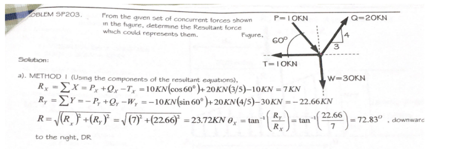
Step by step
Solved in 3 steps with 3 images
- For the spring assemblage shown below, determine the displacement at node 2 and the forces in each spring element. Also determine the force F3. Given: Node 3 displaces an amount 8 = 12.5 mm in the positive x direction because of the force F3 and k1 k2 175 kN/m.A hollow steel crank has an outside diameter of 26 mm and an inside diameter of 21 mm. The load magnitudes are Py = 690 N and Pz = 270 N, and the length dimensions are a = 145 mm, b = 399 mm, and c = 261 mm. Determine the magnitudes of the equivalent forces and the equivalent moments that act at the section that contains point K. (a) Axial force in x direction Px (N (b) Shear force in y direction Vy (N (c) Shear force in z direction Vz (N (d) Torque around x axis Tx (N·m) (e) Bending moment around y axis My (N·m) (f) Bending moment around z axis Mz (N·m) Calculate the section properties for the hollow crank at K. (g) Area A (mm2) (h) Polar moment of inertia J (mm4) (i) Area moment of inertia Iy (and Iz) (mm4) (j) QK (for shear force in y-direction) (mm3) Using the sign conventions, determine the normal and shear stresses that act at K and show these stresses on a stress element. (k) Normal stress in x direction σx(MPa) (l) Normal stress in y direction σy(MPa) (m) Shear stress in x-y…24 - In the cage system connection in the figure; Rod forcesS1= 100 kN,S2= 40 kN,S3= - 60 kN,S4= 50 kN,If S5= 80 kN, Calculate the resultant force acting on joint point D.If the vector representation of the resultant force is R= Rx i + Ry j, Rx = ? Note: The (-) sign of the rod force S3 indicates that the force is pressure. A) 42.43B) -36.36C) -12.93D) 3.64E) 36.36
- Expiremental Method: Force Table F1 - 150N, 30° N of E F2 - 100N, 60° E of S 1) Find the Equilibrant Magnitude and Equilibrant Direction 2) Find Resultant Force Vector Magnitude and %Error 3) Find Resultant Force Vector Direction and %ErrorIt is desired to remove the spike from the timber by appying force along its horizontal axis. An obstruction "A" prevents direct acess, so that two forces, one 400LB and the other "P" are applied by cables as shown. Here we want to investigate the effects of the distance between the spike adn the obstruction on the two forces so replace 8" by "d" in the figure. Determine the magnitude of "P" necessary to insure a resultant "T" directed along the spike. Please show all work and FBD thank you!3.2 determine the force p required to hold the sector gate closed, as shown in figure 3. the width of the gate is 4 m
- The pipe is pulled by three cables as shown on the figure below. All three cables are subjected to known forces. Another cable is planned to be added on the system. This additional cable is designed to pull the pipe along the positive y-axis. The proposed cable, Fy is twice as much as the only force which tends to pull the pipe below the x-axis. (Fa= 7.5kN; Fb= 1.25kN; Fc=5kN) Find the summation of forces in x axis and y axis.Find the magnitude and location of the resultant force on the cylindrical arc shown in Fig. (10) in each of the following two case: a. Pg=120.11 KPa (abs) b. Pg=90.68 KPa (abs) The arc is 25m long (normal to the paper)Q13. As shown in the image below, the member is subjected to the applied loads: a free couple moment M=320lb*ft, concentrated force F1=380lb, and concentrated force F2=220lb. The dimension a=5.5ft. Determine the magnitude of the resulatant moment (in lb*ft) caused by these applied loads about point A. Answer must inculde 1 place after the decimal point.
- The shaft is supported at its ends by two bearings AA and BB and is subjected to the forces applied to the pulleys fixed to the shaft. (Figure 1) The T1=T1= 585-NN forces act in the -zz direction and the 200-NN and 80-NN forces act in the +yy direction. The journal bearings at AA and BB exert only yy and zz components of force on the shaft. Part A Determine the resultant normal force on the cross section at CC. Express your answer to three significant figures and include appropriate units. NC= values ? NC= units? Determine the resultant shear force in the yy direction on the cross section at CC . Express your answer to three significant figures and include appropriate units. (VC)y Values ? (VC)y units ?with the following modifications: Replace the vertical 6kN at point B with a horizontal force 6kN acting to the right at the same point.If the component of a force along x-axis is Fx = 20 kN and along y-axis is Fy = 30 kN, and if “t” is an axis making an angle of 30o in the counter clockwise direction with respect to x-axis, what would be the components of this force Ft and Fn along the orthogonal axes “t” and “n”, respectively? Select one: Ft = 2.32 kN and Fn = 35.98 kN Ft = 15.98 kN and Fn = 32.32 kN Ft = 35.98 kN and Fn = 2.32 kN Ft = 32.32 kN and Fn =15.98 kN