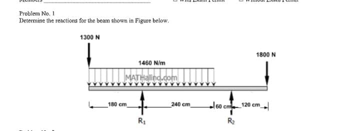
Problem No. 1 Determine the reactions for the beam shown in Figure below, 1300 N 1800 N 1460 N/m MATHalind.com 180 cm _240 cm l60 cm 120 cm R1 R


Q: aZ For Beam loading shown in Fig. Determine the reactions at points A 200 N 200 N 2000 N 730 1m-1m…
A:
Q: 4. Determine the reaction on beams, Rand A: 100(14) 130olb 100 lb 100 Ibst 8' R2
A:
Q: An overhang beam ABC of length 6 m is supported and loaded as shown in Figure Q3.If E = 200 GPa and…
A:
Q: A uniformly distributed load of (20kN/m) acts on a simply supported beam of length 4m. what are the…
A:
Q: a) Plot a graph of beam deflection versus load and calculate the stiffness k of the beam using W 8…
A: we have to determine the stiffness and MOI
Q: The simply supported beam shown below is homogeneous, prismatic and has a distributed axial load of…
A: Triangular loading which is zero at one end and maximum at other is knows as uniformly varying load…
Q: Question 2 A fixed-fixed beam in Figure Q2 1s loaded by a triangularly dıstributed load of maxımum…
A: Draw the free body diagram of the beam as shown in figure.
Q: Question 2 A beam ABC of length 3m has one support at the left end and the other support at a…
A:
Q: 5.8 m S5 x 10 1-beam Part I (a) A S5 x 10 I-beam made of aluminum is loaded by a distributed load of…
A:
Q: 1) Find the support reactions at static equilibrium for the loaded beam shown below in Fig4.1 6'…
A:
Q: Consider a cantilevered, rectangular beam subjected to a load pro- duced by a 1 kg point mass at the…
A:
Q: Beam with cross section area shown in fig (2), the length (L =500 mm), effected by tensile force (F…
A:
Q: For the simply supported beam carrying the concentrated load P = 268 N at its midspan, determine the…
A: Use simply support beam concept to solve this problem, Given information Total length of…
Q: A Simple beam AB supports a concentrated load P acting at distances a and b from the left and right…
A: given; L=a+b lets take reaction force at A =RAlets take reaction force at B =RB
Q: The cantilever beam consists of a rectangular structural steel tube shape [E = 27000 ksi; / = 450…
A:
Q: A simple beam of length L has a clockwise moment M at the left support and half of that moment of…
A:
Q: The deflection curve for a simply supported beam of length L and constant flexural rigidity EI is…
A:
Q: is made of steel material (210GPa) for the beam given below, beam cross section (dimensions mm) is…
A: 1(a) Please refer the drawing from the problem figure For uniformly distributed load, node forms at…
Q: Determine the reactions of the beam shown in the figure. 400N 1000N 1.2m B 0.8m 0.8m
A:
Q: deflection midspan of the simple beam shown in the accompanying illustration. Use Castigliano’s…
A:
Q: A simply supported I-beam is loaded with a distributed load, as shown. The deflection, y, of the…
A:
Q: P B A 21 21 1.50 m 1.50 m 1.50 m 1.50 m
A: given data; ⇒lets take reaction force at A=RA⇒lets take reaction force at…
Q: h L P A cantilever beam has a length L = 8 m and supports a load of P = 9 kN at its free end. The…
A:
Q: Question 2 A propped cantlever beam in Figure Q2 is loaded by a triangularly distrnbuted load of…
A: (2.1)For equilibrium conditions, determine the directions of reactions at points A (RA) and B (RB)…
Q: 10) In the figure shown, the deflection of mercury is initially 250mm. If the pressure at a is…
A: The pressure difference between the point A and point B can be determined as,
Q: modulus E of elasticity, for the ACB beam with inertia I; a) find the elastic curve equation by the…
A:
Q: Problem 2: Determine the support reactions for The beam shown below /2 2N/m 600 N 4N/M 200 N 45 02 m…
A:
Q: (b) L/3 P↓ ↓ L/3 L/3 Draw the deflection of the beam. Where would you expect the maximum deflection?…
A: Given: There are two loads as P are acting apart L/3 distance and of same quantity. Hence from the…
Q: Q1: (a) Derive expressions for the maximum slop and deflection of the cantilever beam shown in…
A: Givencantilever beam W=20kN/mL=2.5mE=205GN/m2I=210×10-6 m4
Q: B. D. AB 45 cm BC 65 cm CD 77 cm RA - 60.25 N Ro 26.43 N P2 -47 N 10 N 5- A student conducted an…
A:
Q: Q1: For the Structure shown in FiG.(1) Determine Reactions at points A,B 30 deg. 10 kN 2 m 2 m 5KNY…
A: (a) The reaction at support A: ◆ Horizontal Reaction: RA,x = 3.5355 kN ◆ Vertical Reaction: RA,y =…
Q: The beam AB in Fig. P-238 supports a load which varies an intensity of 220 N/m to 890 N/m. Calculate…
A: It is required to determine resultant force magnitude and it's location for given loading
Q: Consider the beam shown in (Figure 1). Suppose that w = 880 N/m . Determine the y component of…
A: Apply moment equilibrium at B.
Q: Calculate the deflection of the beam at point C in mm . F1 F2 A B |C 1.5 m 1.5 m →–1.5 m –→–1.5 m
A: The above diagram represents the reactions at…
Q: Modulus E of elasticity, for the ACB beam with inertia I; a- Find the elastic curve equation with…
A: In the question we are required to write the equation for the elastic curve and then find reaction…
Q: Find the support reactions, draw the free-body diagram of the beams that shows the reactions and the…
A: Given: The value of forces are P=2650 N and F=3000 N. The uniform distributed load is w0=1702 N/m…
Q: Determine the reactions of the beam shown in the figure. 400N 1000N 1.2m 0.8m 0.8m.
A:
Q: QI: Determine the reactions at support (A) for the beam loaded as shown in figure. 1.5KN/m 1.5m
A:
Q: A 5º curve intersects a property line CD at point O. The back tangent intersects the property line…
A:
Q: A 10-kg block dropped from 1.5 m onto the center of a simply supported beam with a length 3 m . The…
A:
Q: Example 4.5 Consider the uniform, horizontal beam shown in Fig. 4.29. The beam is fixed at point A…
A:
Q: The data for the uniform beam shown in Fig. 2.42 are given by L= 100 cm, P= 1000 N, E = 70 × 10’ Pa,…
A:
Q: 2- For the beam shown below The moment of inertia = / and the elastic modulus E a) Find the reaction…
A:
Q: Qq Determine the deflection at point C for the beam shown in Figure 1. Use E= 1.2 MN.m². 15 kN 12…
A:
Q: Consider the beam and loading shown where L=990 N/m. NOTE: This Is a multi-part question. Once an…
A:
Q: Part A Consider the beam shown in (Figure 1). Suppose that w = 640 N/m Determine the y component of…
A:

Step by step
Solved in 4 steps

- Calculate first the formula and then the value of the angle of rotation and deflection of the beam with a length of 3m at the point C. L = 2.1m , A= 0.9m E=210GPa I=119x106mm4In the figure shown, the deflection of mercury is initially 250mm. If the pressure at a is increased by 40kPa, while maintaining the pressure at b constant, what will be the new mercury deflection?Textbook: Statics and Strengths of Materials, 6th EditionProblem: Chapter 13, Problem 13.3AURL: https://www.bartleby.com/solution-answer/shear-and-bending-moment-in-beams-6th-edition/9780133840544/b8786dd2-35c0-11e9-8385-02ee952b546e "Calculate the reactions at points A and B for the beams shown." For this problem, the answerer got:RA = 33.5 kips upwardsRB = 29.5 kips upwards I got:RA = 19.2 kips upwardsRB = 4.8 kips upwards The answer stops at:RA + 4.8 = 24RA = 19.2 kips I just don't see where the other numbers came from.
- Draw the influence lines for the vertical reactions at supports A and E and the reaction moment at support E of the beam shown in Fig. P8.13.Question 1) in FIG loading condition is given beam F force F = 65 kN , first distributed load W 1 = 41 kN / m , w 2 distributed load w 2 = 51 kN / m , θ angle θ = 48 ° and L length of L = 5 m . According to this; Question 1-A) B at the point y direction ( B y ) Determine the support reactions. (Enter yourresultwithout writing kN units.) Question 1-B) to the point in y direction ( A y ) Determine the support reactions. ( Enter yourresult without writing kN units.) Question 1-C) to the point in x direction ( A x ) Determine the support reactions. ( Enter yourresult without writing kN units.)Please don't provide handwritten solution ..... Design the cross section of the beam such that the maximum deflection is < 2 mm. Assume E=200 GPa and the beam cross section to be square.
- answer this ; Let ? represent the reaction force at Support B. By releasing the beam at Support B and imposing a force ? at Point B, the deflection of the beam consists of two parts,i.e. Part I- the deflection caused by ?? ; Part II- the deflection caused by ? Please treat R, w, h , L , E as variables in this step , the mathematical equation for the deflection at Point B caused by ? ( Part II) can be written as (Hint : to input equation ?2??2?ℎ , you can type (R^2*L)/(Q^2*w*h) )Describe what is the section modulus of the beams and its importance. Describe the formula for the section modulusIn the figure shown below, the deflection of mercury is initially 250mm . If the pressure at A is increased by 33kpa , while maintaining the pressure at B constant, what will be the new mercury deflection? Pls answer and explain in detailed
- Determine the maximum deflection of a simply supported beam carrying a hydraulic cylinder in a machine used to press bushings into a casting as shown in the figure. The force exerted during the pressing operation in 45 kN. The beam is rectangular, 35 mm thick and 150 mm high, and made of steel (E = 207 Gpa).How can the equation of the elastic curve and its slope be obtained?Before obtaining the slope and deflection at any point on the elastic curve, why is it necessary to relate the internal moment to the radius of curvature?