Q1) A beam with a cross-section shown in figure 1 is loaded in such a way that the maximum moments are +1.0P lb-ft an -1.5P lb-ft, where P is the applied load in ponds. Determine the maximum safe value of P if the working stress es are 4 ksi in tension and 10 ksi in compression. 2.5 in - N.A. 4.0 in Im = 192 in Figure 1
Q: Q1) A simply supported beam is 3 m long and carries a vertical load of 5 kN at point Im from the…
A: Given: The forces acting on the beam are as:
Q: 2.3. The wooden box beam shown in figure (3a) is fabricated from four boards fastened together with…
A: Solved below
Q: Question 1) F=16 kN single load, M=22 kN.m moment and w=11 kN/m distributed load are acting on the…
A: As per the guidelines we will answer the first three subparts for you. for the rest of the subparts…
Q: Design a timber glue-lam beam made from douglas fir for the given load in the figure below. 670…
A:
Q: Since the allowable normal stress of AC beam loaded with uniformly distributed load is 100MPa in…
A:
Q: I. Problem Solving. Box your final answer. 1. Find the (a) maximum tensile and compressive bending…
A:
Q: QUESTION 1 A beam of rectangular section as shown in Figure 1 carries a load of 2 kN at mid-span.…
A: Givensimply supported beam as shown in figure below-F=2kNL=3.6md=2bσblimit=9N/mm2
Q: Question 1) F=35 kN single load, M=45 kN.m moment and w=16 kN/m distributed load are acting on the…
A: A pin support will exert both horizontal and vertical components of reaction. The support A is pin…
Q: he cross section of a reinforced concrete beam is shown below. It has a modular ratio of 15. If the…
A: Givenm=15σcb=6N/mm2σst=120N/mm2
Q: Useful equations; o = E A 1. The steel shaft carries the axial loads as shown in the figure below.…
A: Given axial load action on stepped shaft as shown below
Q: 334. A beam simply supported at the ends has the cross section and is leaded with a concentrated…
A: When a beam is loaded it tends to bend and a bending moment acts upon it. As a result, longitudinal…
Q: 6.2-2 A wood beam is strengthened using two steel plates as shown in Fig. a. The beam has simple…
A: Given, Youngs modulus of wood, EW=11GPa. Youngs modulus of steel, ES=200GPa The moment of inertia of…
Q: Q2: A simply supported beam has a span of 4m and carries a uniformly distributed load of 60 kN/m…
A: Given data: The uniformly distributed load is w = 60 kN/m and span of L = 4 m. The concentrated…
Q: 700N M-150UNm 2m 3m For the above dlagram, given that F, - 450 N. 0-45 degrees and d-5 m calculate…
A:
Q: 1. Distance between top of the beam to Neutral Axis or "c top". 2. Moment of Inertia at Neutral Axis…
A:
Q: Q2 A beam of 4-m span is in the form of a cross bar as shown in Fig. (2) It carries a uniformly…
A:
Q: To analyze a beam subjected to a vertical force and a triangular distributed load, determine the…
A:
Q: Situation 12: The simply supported beam in FIGURE SOM-008 is fabricated by gluing together three 160…
A: For the given simply supported beam maximum bending stress in the planks = 24 MPa To determine…
Q: Since the safe normal stress of the wood used for the beam and loading condition shown in the figure…
A:
Q: A loaded beam, 60 mm wide by 100 mm high and 6 m long, has the shear and moment diagrams as shown…
A: Given: The width of beam, b = 60 mm = 0.06 m The height of beam, h = 100 mm = 0.1 m The length of…
Q: A weight of 120ON is dropped vertically at the middle of a beam 50mmx250mm * and 6m long simply…
A: Find the height of weight that must be dropped from.
Q: At certain sections (0 through 7) a beam has the cross-section shown in the following Figure. The…
A:
Q: As the safe normal stress of the wood used for the beam and loading condition shown in the figure is…
A:
Q: F L h Figure Q1 b) State if the cantilever beam is in plain stress or plain strain and explain…
A: given; lets take width of beam=b lets take reaction force=R
Q: Q1 Calculate the bending stresses at top and bottom fibers of a simply supported beam and loaded as…
A:
Q: Figure Q1 shows one ‘L’ shaped beam ACD which is built-in at one end. It is loaded with load F=3 kN…
A:
Q: For the beams shown in Figure 3.5, draw the shear diagrams and note all critical values for shear.…
A: An equivalent load of uniformly distributed load refers to the single load which can be used to…
Q: In the Figure shown, the rigid beam with negligible mass was horizontal before the load P was…
A: Given, As = 600 mm2Es = 200 GPa = 200,000 N/mm2Ls = 2 m = 2000 mmAa = 900 mm2Ea = 70 GPa = 70,000…
Q: To analyze a beam subjected to a vertical force and a triangular distributed load, determine the…
A:
Q: Q1: At a certain section, beam has the cross-section shown in Figure (1) below. The beam is simply…
A:
Q: a) b) c) A loaded cantilever beam is shown in Figure 3. Determine the horizontal and vertical…
A:
Q: 13. A steel cantilever beam, as shown in Fig. 6.21, is subjected to a transverse load at its end th…
A:
Q: (B) // The straight beam with distribution load as shown in figure B is simply supported by a pin at…
A:
Q: 1. Find the maximum tensile and compressive flexural stresses for the cantilever beam with loading…
A:
Q: he allowable normal stress of AC beam loaded with uniformly distributed load is 100MPa in tensile,…
A: we will calculate the reactions first
Q: The beam shown below is subjected to an applied moment of 8kNm and a uniformly distributed load of…
A:
Q: Calculate maximum compressive strain on circular beam with an outside diameter of 80mm and wall…
A:
Q: rigid beam with negligible weight is pinned at one end and attached to two vertical rods. The beam…
A: Givenlength of span L=10ftarea of bronze Ab=4in2young modulus of bronze Eb=12×106psilength of bronze…
Q: Consider the beam and loading shown. The allowable normal stress for the steel used is 152 MPa.…
A: Given Data The allowable normal stress acting on the steel is: σ=152 MPa The load acting on the…
Q: A bracket with a basic shape cross-section is loaded as shown in Fig. Q: Determine the following: a)…
A:
Q: Question 5 a) What is the importance of SFD and BMDs for structural engineers? b) For the beam and…
A:
Q: A thin-wall circular section beam has a diameter of 200 mm and is 1 m long. One end of the beam is…
A:
Q: As the safe normal stress of the wood used for the beam and loading condition shown in the figure is…
A:
Q: Question 1) F=35 kN single load, M=45 kN.m moment and w=16 kN/m distributed load are acting on the…
A:
Q: A uniformly distributed load of 200 lb/ft is carried on a simply supported span. If the cross…
A:
Q: 2. A cantilever, made of a certain material, of 2 m length and square section 212 mm on its side,…
A: Given:Lc=2 mac=212mmP=13,252NLs=3mbs=150mmds=300mm
Q: simply supported beam with a length of 4m is loaded with a uniform distributed load (w). The beam…
A:
Q: 4.10 (A/B). A composite beam is of the construction shown in Fig. 4.28. Calculate the allowable…
A:
Q: 1002/ A timber beam is reinforced with Steel Plates rigidly attached at the top and bottom as shown…
A:
Q: Q3/ Fig. 3 shows a cost iron bracket of cross-section of I-form. Determine the maximum bending…
A:
Please solve the question and avoid pilagrism thanks.....
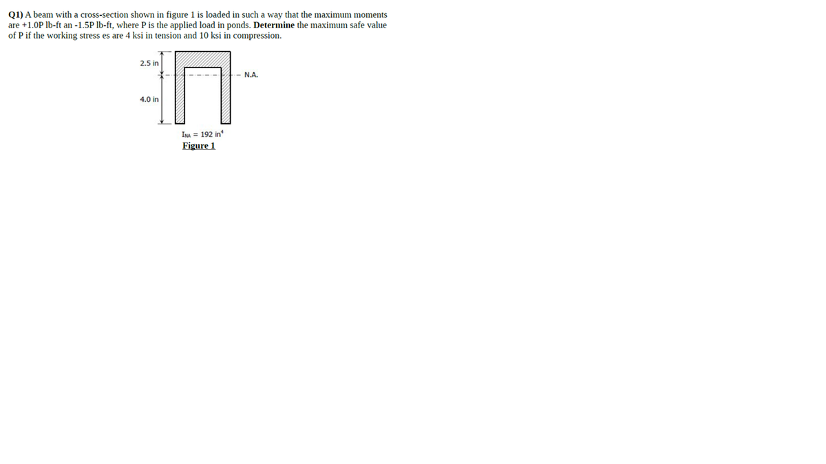
Trending now
This is a popular solution!
Step by step
Solved in 4 steps
- A flying but tress transmit s a load P = 25 kN, acting at an angle of 60º to the horizontal, to the top of a vertical buttress AB (see figure). The vertical buttress has height h = 5.0 m and rectangular cross section of thickness t = 1.5 m and width b = 1.0 m (perpendicular to the plane of the figure). The stone used in the construction weighs y = 26 kN/m3. What is the required weight W of the pedestal and statue above the vertical buttress (that is, above section A) to avoid any tensile stresses in the vertical buttress?A wood beam is strengthened using two steel plates as shown in Fig, a. The beam has simple supports and an overhang and is subjected to a point load and a uniform load as shown in Fig. b. Calculate the maximum tensile and compressive stresses of the beam. Assume that Ew= 11 GPa and Es= 200 GPa.A bridge girder A B on a simple span of length L = 14 m supports a distributed load of maximum intensity q at m id-span and minimum intensity q/2 at supports A and B that includes the weight of the girder (sec figure). The girder is constructed of three plates welded to form the cross section shown. Determine the maximum permissible load q based upon (a) an a I lowable bending stress tra]Um = 110 M Pa and (b) an allowable shear stress r ,. = 50 M Pa.
- A simply supported beam is subjected to a in early varying distributed load q(x)=xL with maximum intensity q0at B. The beam has a length L = 4 m and rectangular cross section with a width of 200 mm and height of 300 mm. Determine the maximum permissible value for the maximum intensity, q0, if the allowable normal stresses in tension and compression are 120 M Pa.An S6 × 12.5 steel cantilever beam AB is supported by a steel tic rod at B as shown. The tie rod is just taut when a roller support is added at Cat a distance s to the left of £, then the distributed load q is applied to beam segment AC, Assume E = 30 × 106 psi and neglect the self-weight of the beam and tie rod. Sec Table F-2(a) in Appendix F for the properties of the S-shape beam. (a) What value of uniform load q will, if exceeded, result in buckling of the tie rod if L1, =6 ft, s = 2 ft, H = 3 ft, and d = 0.25 in.? (b) What minimum beam moment of inertia ibis required to prevent buckling of the tie rod if q = 200 lb/ft, L1, = 6 ft, H = 3 ft, d = 0.25 in., and s = 2 ft? (c) For what distance s will the tic rod be just on the verge of buckling if q = 200 lb/ft, L1= 6 ft, M = 3 ft, and d = 0.25 in.?A cantilever beam, a C12 x 30 section, is subjected to its own weight and a point load at B. Find the maximum permissible value of load f at B (kips) if the allowable stress in tension and compression is o\. =18 ksi.
- A two-story building has steel columns AB in the first floor and BC in the second floor, as shown in the figure. The roof load P:equals 400 KN, and the second-floor load P-, equals 720 kN. Each column has a length L = 3.75 m. The cross-sectional areas of the first- and second-floor columns are 11,000 mm" and 3900 mm", respectively. (a) Assuming that E = 206 GPa. determine the total shortenings aof the two columns due to the combined action of the loads Ptand P,. (b) How much additional load P0can be placed at t he top of t he column (point C) if t he total shortening: SACis not to exceed 4.0 mm?A steel bar has a square cross section of width b = 2.0 in. (sec figure). The bar has pinned supports at the ends and is 3.0 ft long. The axial forces acting at the end of the bar have a resultant P = 20 kips located at distance e = 0,75 in, from the center of the cross section. Also, the modulus of elasticity of the steel is 29,000 ksi. Determine the maximum compressive stress max, in the bar. If the allowable stress in the steel is 18,000 psi, what is the maximum permissible length Lmaxof the bar?The cross section of a narrow-gage railway bridge is shown in part a of the figure. The bridge is constructed with longitudinal steel grinders that support the wood cross ties. The bridge is constructed with longitudinal steel girders that support the wood cross ties. The girders are restrained against lateral buckling by diagonal bracing, as indicated by the dashed lines. The spacing of the girders is S1= 50 in. and the spacing of the rails is s2= 30 in. The load transmitted by each rail to a single tie is P = 1500 1b. The cross section of a tie, shown in part b of the figure, has a width b =5.0 in. and depth d. Determine the minimum value of d based upon an allowable bending stress of 1125 psi in the wood tie. (Disregard the weight of the tie itself.)
- An elevated jogging track is supported at intervals by a wood beam AB (L = 7.5 ft) that is pinned at A and supported by steel rod BC and a steel washer at B. Both the rod (dBC= 3/16 in.) and the washer (dB= 1.0 in.) were designed using a rod tension force of TBC=415 lb. The rod was sized using a factor of safely of 3 against reaching the ultimate stress tru— 60 ksi. An allowable bearing stress sba= 565 psi was used to size the washer at B. A small platform HF is suspended below a section of the elevated track to support some mechanical and electrical equipment. The equipment load is uniform load q = 50 lb/ft and concentrated load WE= 175 lb at mid-span of beam HF. The plan is to drill a hole through beam ABaX £land install the same rod (dBC) and washer) dB) at both D and F to support beam HF. (a) Use s and to check the proposed design for rod DF and washer d,: are they acceptable? (b) Re-check the normal tensile stress in rod BC and bearing stress at 8 if either is inadequate under the additional load from platform HF. Re-design them to meet the original design criteria.A retaining wall (Fig. a) is constructed using steel W-shape columns and concrete panel infill (Fig, b). Each column is subjected to lateral soil pressure with peak intensity q0(Figs, b and c). The tensile and compressive strength of the beam is 600 MPa. Select the most economical W 360 section from Table F-l(b) based on safety factor of 3.0.Two bars AC and BC of the same material support a vertical load P (see figure). The length L of the horizontal bar is fixed, but the angle fl can be varied by moving support A vertically and changing the length of bar AC to correspond with the new position of support A. The allowable stresses in the bars are the same in tension and compression. When the angle ft is reduced, bar AC becomes shorter, but the cross-sectional areas of both bars increase because the axial forces are larger. The opposite effects occur if the angle 0 is increased. Thus, the weight of the structure (which is proportional to the volume) depends upon the angle ft. Determine the angle ft so that the structure has minimum weight without exceeding the allowable stresses in the bars. Note: The weights of the bars are very small compared to the force P and may be disregarded.