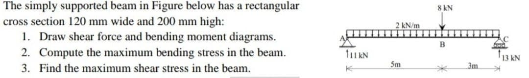
simply supported beam in Figure below has a rectangular s section 120 mm wide and 200 mm high: 1. Draw shear force and bending moment diagrams. 2. Compute the maximum bending stress in the beam. 3. Find the maximum shear stress in the beam.


Q: A beam ABCDE is 5 m in length and loaded as shown in Figure Q3. Draw the S.F. and B.M. diagrams for…
A: The maximum bending stress occurs at the maximum bending moment and is given by,…
Q: Homework; In Figure below, a cantilever beam is subjected to an inclined force (P); calculate: 1-…
A:
Q: For the loaded beam shown in Figure Q6 below, consider section M-M and detemine the following: 6.1…
A: Given Data: Length of the beam, L=0.4+0.3+0.4=1.1 m
Q: A rectangular plate with notches (see figure) has dimensions h=5.75 in, h1 = 5 in and the plate…
A:
Q: A bending moment of M=150 kips-in is applied at the cross section of beam shown in Figure Question…
A:
Q: Figure 4 shows a simply supported timber beam AB with 4.5 m long carrying the uniformly distributed…
A:
Q: В C 3 m 3 m
A:
Q: A simply supported beam ABCD is subjected to a linearly distributed load, with wo = 100 N/m, two…
A:
Q: A beam ABCDE is 5 m in length and loaded as shown in Figure Q3. Draw the S.F. and B.M. diagrams for…
A:
Q: The cross-sectional dimensions of the beam shown in Figure are ro = 115 mm and ri = 95 mm. Given Mz…
A: Moment of inertia is given asI=π64D4-d4I=π642×1154-2×954I=73.39×106 mm4perpenficular distance…
Q: Q: Find the value of W which can be applied to the beam shown in figure below. if the maximum…
A:
Q: A beam with rigid support at A, pin connection at C and roller at D has the geometry and loads as…
A:
Q: Example 4 The simply supported beam in Figure below has a rectangular 3kN cross section 100 mm wide…
A: Given: Uniform distributed load at the beam is, w=1.5 kN/m . Point load acting at point B is 3 kN .…
Q: Ex: For the T beam subjected to distributed load (W), shown in figure,, the beam material can resist…
A:
Q: Example 4 The simply supported beam in Figure below has a rectangular 3kN cross section 100 mm wide…
A: Solution: To find support reactions at A and B, considering static equilibrium,…
Q: The simple beam ACB shown in the figure is subjected to a concentrated load P 30 kips and a…
A: Given: Distributed load (q)=3kips/ftConcentrated load (P)=30kips
Q: 1. A cantilever beam supporting two concentrated loads at points A and B, is shown in Figure 1.…
A:
Q: The composite beam in the figure is made of steel and aluminum. Beam In steel and aluminum as it is…
A: Given: Esteel=210GPa Eal=70GPa M=2kNm Solution: The position of the neutral axix is exactly at the…
Q: Problem 1) Cross section of a beam was shown in the below figure. Suppose that this beam is…
A: Given: The bending moment, M = 10 kN.m
Q: The simply supported beam AB as shown in Figure Q3(a) has a uniform load of intensity, w - 15 kN/m…
A: Given we have w=15 KN/mINA=3.6 X 106 mm4RA=RB (symmetric loading)⇒RA+RB=15(0.6+1.8)⇒ZRA=1.5 X…
Q: The cross-section of beam shown in Figure Q2 (centroid in red) is subjected to pure bending. Taking…
A:
Q: For the beam shown in figure below, draw the shear force and bending moment.
A:
Q: Find the absolute maximum bending stress in the beam shown in the figure below. (Figure 3) The beam…
A:
Q: Find the maximum transverse shear stress in the thin walled box beam shown in the figure below. This…
A:
Q: Q2: For the beam shown in figure below, find the bending stress of beam at point A. When I= 120*10*…
A: Bending equation is given as: MI=σy=ER where, M is the bending moment I is the moment of…
Q: 3-In the figure given below, P(load) and M(moment) effects from the mid point of the fixed beam from…
A: given data;load =Pmoment =MEI=constantlength of beam(l)=2Llets take reaction force at A=RA take…
Q: In the simple beam given in the figure, Find the maximum slope and depression using the values.…
A: When any beam is subjected to a load, it deflects, and the neutral axis becomes a curved line which…
Q: The simply supported beam in Figure below has a rectangular cross section 100 mm wide and 200 mm…
A:
Q: Ex: For a simple beam of length (L) subject to a concentrated load (P), shown in figure, Find : 1.…
A: Since, all the three parts are different question. And, as per the guidelines, I can solve only one…
Q: beam ABCDE is 5 m in length and loaded as shown in Figure Q3. Draw the S.F. and B.M. diagrams for…
A:
Q: For the simply supported beam shown in the figure, if (q=30 KN/m) and (L=6m), then, the point of…
A: Consider the free body diagram of the beam as shown below. The distributed load can be assumed to…
Q: For the cantilever beam with uniformly distributed load shown in Figure find: a. The maximum shear…
A: note: according to Bartleby guideline, we solve the first three-part of the question please repost…
Q: A steel beam ABC carries a uniformly distributed load of w (kN/m) over the unsupported length BC, as…
A:
Q: Q3/ The beam shown in figure(3). carrying triangle distributed load 20KN/m and concentrated load…
A: Drawing the free body diagram of the beam as shown below, The triangular load can be written as,…
Q: For the simply supported beam with square cross sectional area as shown in the figure below: 1.…
A: The summation of force along vertically is given as, ∑Fy=0RA+RB=3 kN+2 kN+5 kNRA+RB=10 kN Taking…
Q: 5.8-6) A cantilever beam of length L = 2 m sup- ports a load P = 8.0 kN (see figure). The beam is…
A:
Q: Q6 The simply supported beam in Figure below has circular cross section of 60 mm as shown in Figure…
A: In the given problem, we have to find maximum bending moment to find maximum bending stress and max…
Q: 3-In the figure given below, P(load) and M(moment) effects from the mid point of the fixed beam from…
A:
Q: Let's consider a simple supported beam subjected to a triangular distributed load and a couple…
A: Answer is M(x) = -83.3 X3 - 166.7 X ( N.m)
Q: Draw diagram shear force and bending moment to cantilever beam which shown in the figure. W=5 KN/m…
A: The Shear Force Diagram (SFD) and Bending Moment Diagram (BMD) are very important tools to analyze a…
Q: A simply supported beam hinged at A and supported at C, is carrying a distributed load and a point…
A: Note: Company policy does not allow to answer more than three subparts. So answer of first three…
Q: A wide-flange beam (see figure) is subjected to a shear force V. h h Using the following dimensions…
A:
Q: The Cantilever beam in Fig. 5, has a circular cross section (diameter 100 mm) (a)find the shear…
A: Given data, d = Diameter of the circular cross-section = 100 mm w = Intensity of the uniform load =…
Q: Q: For the cantilever beam with uniformly distributed load shown in Figure find; a The maximum shear…
A: As per company policy, we are restricted to solve only the first three sub-part of one question at a…
Q: Let's consider a fixed supported beam subjected to a triangular distributed load as shown in the…
A:
Q: (a) Square Beam AB having the circular hollow cross-section as shown in Figure Qla and it is loaded…
A: Since you have asked multiple questions, we will solve the first question for you. If you want any…
Q: A composite beam consisting of fiberglass faces and a core of particle board has the cross section…
A:
Q: * The hollow circle cross section of the simply supported beam shown in the figure. Find the maximum…
A: For solution refer below images.
Q: The cross-sectional dimensions of the beam shown in Figure are ro = 115 mm and ri = 95 mm. Given Mz…
A:

Step by step
Solved in 2 steps with 2 images


- -1 through 5.10-6 A wide-flange beam (see figure) is subjected to a shear force V. Using the dimensions of the cross section, calculate the moment of inertia and then determine the following quantities: The maximum shear stress tinixin the web. The minimum shear stress rmin in the web. The average shear stress t (obtained by dividing the shear force by the area of the web) and the ratio tmax/taver. The shear force Vweb/V carried in the web and the Vweb/V. Note: Disregard the fillets at the junctions of the web and flanges and determine all quantities, including the moment of inertia, by considering the cross section to consist of three rectangles. 5.10-1 Dimensions of cross section: b = 6 in,, ï = 0.5 in., h = 12 in,, A, = 10.5 in., and V = 30 k.-1 through 5.10-6 A wide-flange beam (see figure) is subjected to a shear force V. Using the dimensions of the cross section, calculate the moment of inertia and then determine the following quantities: The maximum shear stress tinixin the web. The minimum shear stress rmin in the web. The average shear stress raver (obtained by dividing the shear force by the area of the web) and the ratio i^/t^ The shear force carried in the web and the ratio V^tV. Noie: Disregard the fillets at the junctions of the web and flanges and determine all quantities, including the moment of inertia, by considering the cross section to consist of three rectangles. 5.10-3 Wide-flange shape, W 8 x 28 (see Table F-L Appendix F); V = 10 k-1 through 5.10-6 A wide-flange beam (see figure) is subjected to a shear force V. Using the dimensions of the cross section, calculate the moment of inertia and then determine the following quantities: The maximum shear stress tinixin the web. The minimum shear stress rmin in the web. The average shear stress raver (obtained by dividing the shear force by the area of the web) and the ratio i^/t^ The shear force carried in the web and the ratio V^tV. Note: Disregard the fillets at the junctions of the web and flanges and determine all quantities, including the moment of inertia, by considering the cross section to consist of three rectangles. 5.10-4 Dimensions of cross section: b = 220 mm, f = 12 mm, h = 600 mm, hx= 570 mm, and V = 200 kN.
- -1 through 5.10-6 A wide-flange beam (see figure) is subjected to a shear force V. Using the dimensions of the cross section, calculate the moment of inertia and then determine the following quantities: The maximum shear stress tinixin the web. The minimum shear stress rmin in the web. The average shear stress raver (obtained by dividing the shear force by the area of the web) and the ratio i^/t^. The shear force i^/t^ carried in the web and the ratio V^tV. Note: Disregard the fillets at the junctions of the web and flanges and determine all quantities, including the moment of inertia, by considering the cross section to consist of three rectangles. 5.10-6 Dimensions of cross section: b = 120 mm, a = 7 mm, h = 350 mm, hx= 330 mm, and K=60kN.-1 through 5.10-6 A wide-flange beam (see figure) is subjected to a shear force V. Using the dimensions of the cross section, calculate the moment of inertia and then determine the following quantities: The maximum shear stress tinixin the web. The minimum shear stress rmin in the web. The average shear stress raver (obtained by dividing the shear force by the area of the web) and the ratio i^/t^ The shear force carried in the web and the ratio K b/K. Note: Disregard the fillets at the junctions of the web and flanges and determine all quantities, including the moment of inertia, by considering the cross section to consist of three rectangles. 5.10-2 Dimensions of cross section: b = 180 mm, v = 12 mm, h = 420 mm, i = 380 mm, and V = 125 kN.Beam ABCD represents a reinforced-concrete foundation beam that supports a uniform load of intensity q1= 3500 lb/ft (see figure). Assume that the soil pressure on the underside of the beam is uniformly distributed with intensity q2 Find the shear force VBand bending moment MBat point B. Find the shear force Vmand bending moment M at the midpoint of the beam.
- A steel beam of length L = 16 in. and cross-sectional dimensions h = 0.6 in. and h = 2 in. (see figure) supports a uniform load of intensity if = 240 lb/in., which includes the weight of the beam. Calculate the shear stresses in the beam (at the cross section of maximum shear force) at points located 1/4 in., 1/2 in., 3/4 in., and I in, from the top surface of the beam. From these calculations, plot a graph showing the distribution of shear stresses from top to bottom of the beam.Cantilever beam AB carries an upward uniform load of intensity q1from x = 0 to L/2 (see Fig. a) and a downward uniform load of intensity q from x = L/2 to L. Find q1in terms of q if the resulting moment at A is zero. Draw V and M diagrams for the case of both q and qtas applied loadings. Repeat part (a) for the case of an upward triangularly distributed load with peak intensity q0(see Fig. b). For part (b), find q0, instead of q1A beam ABCD with a vertical arm CE is supported as a simple beam at .1 and D (see figure). A cable passes over a small pulley that is attached to the arm at E. One end of the cable is attached to the beam at point B. The tensile force in the cable is 1800 lb. Draw the shear-Force and bending-moment diagrams for beam A BCD. Note: Disregard the widths of the beam and vertical arm and use centerline dimensions when making calculations. Repeat part (a) if a roller support is added at C and a shear release is inserted just left of C (see figure part b).
- A beam with a channel section is subjected to a bending moment M having its vector at an angle 8 to the 2 axis (see figure). Determine the orientation of the neutral axis and calculate the maximum tensile stress tt and maximum compressive stress crc in the beam. Use a C 200 × 20.5 channel section with M = 0.75 kN - m and 0 = 20°.At a full d raw, an archer applies a pull of 130 N to the bowstring of the bow shown in the figure. Determine the bending moment at the midpoint of the bow.A beam of wide-flange shape, W 8 x 28, has the cross section shown in the figure. The dimensions are b = 6.54 in., h = 8.06 in., fw = 0.285 in., and tf = 0.465 in.. The loads on the beam produce a shear force V = 7.5 kips at the cross section under consideration. Use center line dimensions to calculate the maximum shear stress raiaxin the web of the beam. Use the more exact analysis of Section 5,10 in Chapter 5 to calculate the maximum shear stress in the web of the beam and compare it with the stress obtained in part .