Q2/ Find diagram for shear force and moment of EFGH beam as shown in figure below. 20 KN 3 A, 4 400 cm 400 cm 400 cm 400 cm F G H 400 cm B 28 KN
Q2/ Find diagram for shear force and moment of EFGH beam as shown in figure below. 20 KN 3 A, 4 400 cm 400 cm 400 cm 400 cm F G H 400 cm B 28 KN

Mechanics of Materials (MindTap Course List)
9th Edition
ISBN:9781337093347
Author:Barry J. Goodno, James M. Gere
Publisher:Barry J. Goodno, James M. Gere
Chapter5: Stresses In Beams (basic Topics)
Section: Chapter Questions
Problem 5.5.18P: Determine the maximum tensile stress erand maximum compressive stress ecdue to the load P acting on...

Related questions
Question
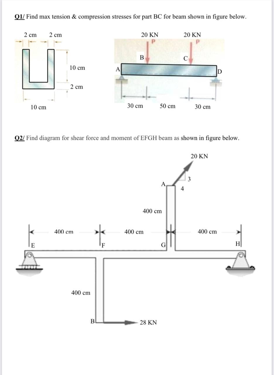
Transcribed Image Text:Q1/ Find max tension & compression stresses for part BC for beam shown in figure below.
20 KN
20 KN
2 cm
2 cm
B
10 cm
A
D
2 cm
30 cm
50 cm
30 cm
10 cm
Q2/ Find diagram for shear force and moment of EFGH beam as shown in figure below.
20 KN
3
A
4
400 cm
400 cm
400 cm
400 cm
H
'F
400 cm
B
28 KN
Expert Solution
This question has been solved!
Explore an expertly crafted, step-by-step solution for a thorough understanding of key concepts.

Step by step
Solved in 4 steps with 4 images

Knowledge Booster


Learn more about
Need a deep-dive on the concept behind this application? Look no further. Learn more about this topic, mechanical-engineering and related others by exploring similar questions and additional content below.Recommended textbooks for you
Mechanics of Materials (MindTap Course List)
Mechanical Engineering
ISBN:
9781337093347
Author:
Barry J. Goodno, James M. Gere
Publisher:
Cengage Learning
Mechanics of Materials (MindTap Course List)
Mechanical Engineering
ISBN:
9781337093347
Author:
Barry J. Goodno, James M. Gere
Publisher:
Cengage Learning