Q2. The single-line diagram of a simple three-bi is shown in Figure-2. Each generator is repres- behind the sub-transient reactance. All expressed in per unit on a common MVÀ base and shunt capacitances are neglected. The onoroting no lood ot thoir rotod voltogo
Q2. The single-line diagram of a simple three-bi is shown in Figure-2. Each generator is repres- behind the sub-transient reactance. All expressed in per unit on a common MVÀ base and shunt capacitances are neglected. The onoroting no lood ot thoir rotod voltogo

Power System Analysis and Design (MindTap Course List)
6th Edition
ISBN:9781305632134
Author:J. Duncan Glover, Thomas Overbye, Mulukutla S. Sarma
Publisher:J. Duncan Glover, Thomas Overbye, Mulukutla S. Sarma
Chapter9: Unsymmetrical Faults
Section: Chapter Questions
Problem 9.13P: Consider the oneline diagram of a simple power system shown in Figure 9.20. System data in per-unit...

Related questions

Concept explainers
Three-Phase Transformers
Three-segment transformers are a type of transformer used to transform voltages of electrical systems into three ranges. Two type transformers are shell-type transformer and core type transformer. In brief, it could be described because of the exquisite kinds of configurations.
Transformer
Ever since electricity has been created, people have started using it in its entirety. We see many types of Transformers in the neighborhoods. Some are smaller in size and some are very large. They are used according to their requirements. Many of us have seen the electrical transformer but they do not know what work they are engaged in.
Question
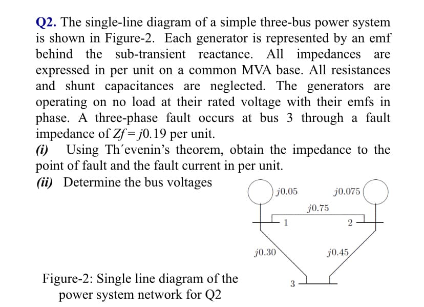
Transcribed Image Text:Q2. The single-line diagram of a simple three-bus power system
is shown in Figure-2. Each generator is represented by an emf
behind the sub-transient reactance. All impedances are
expressed in per unit on a common MVA base. All resistances
and shunt capacitances are neglected. The generators are
operating on no load at their rated voltage with their emfs in
phase. A three-phase fault occurs at bus 3 through a fault
impedance of Zf = j0.19 per unit.
(i) Using Th'evenin's theorem, obtain the impedance to the
point of fault and the fault current in
(ii) Determine the bus voltages
per
unit.
) j0.05
j0.075
j0.75
2
j0.30
j0.45
Figure-2: Single line diagram of the
power system network for Q2
3
Expert Solution
This question has been solved!
Explore an expertly crafted, step-by-step solution for a thorough understanding of key concepts.

Step by step
Solved in 4 steps with 2 images

Knowledge Booster


Learn more about
Need a deep-dive on the concept behind this application? Look no further. Learn more about this topic, electrical-engineering and related others by exploring similar questions and additional content below.Recommended textbooks for you
Power System Analysis and Design (MindTap Course …
Electrical Engineering
ISBN:
9781305632134
Author:
J. Duncan Glover, Thomas Overbye, Mulukutla S. Sarma
Publisher:
Cengage Learning

Power System Analysis and Design (MindTap Course …
Electrical Engineering
ISBN:
9781305632134
Author:
J. Duncan Glover, Thomas Overbye, Mulukutla S. Sarma
Publisher:
Cengage Learning