Q3- A single-phase half-wave controlled rectifier connected to 200V, 50HZ supply to feed load resistor 10 n. If the fire angle a=90°. Calculate and draw the following: a- DC Power b- AC Power c- The rectification efficiency
Q3- A single-phase half-wave controlled rectifier connected to 200V, 50HZ supply to feed load resistor 10 n. If the fire angle a=90°. Calculate and draw the following: a- DC Power b- AC Power c- The rectification efficiency

Chapter59: Motor Startup And Troubleshooting Basics
Section: Chapter Questions
Problem 12SQ: How is a solid-state diode tested? Explain.

Related questions
Question
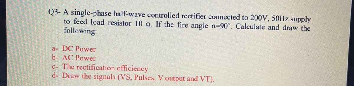
Transcribed Image Text:Q3- A single-phase half-wave controlled rectifier connected to 200V, 50HZ supply
to feed load resistor 10 n. If the fire angle a=90°. Calculate and draw the
following:
a- DC Power
b- AC Power
c- The rectification efficiency
d- Draw the signals (VS, Pulses, V output and VT).
Expert Solution
This question has been solved!
Explore an expertly crafted, step-by-step solution for a thorough understanding of key concepts.

Step by step
Solved in 2 steps with 1 images

Knowledge Booster


Learn more about
Need a deep-dive on the concept behind this application? Look no further. Learn more about this topic, electrical-engineering and related others by exploring similar questions and additional content below.Recommended textbooks for you

Delmar's Standard Textbook Of Electricity
Electrical Engineering
ISBN:
9781337900348
Author:
Stephen L. Herman
Publisher:
Cengage Learning
Delmar's Standard Textbook Of Electricity
Electrical Engineering
ISBN:
9781337900348
Author:
Stephen L. Herman
Publisher:
Cengage Learning