Q3 
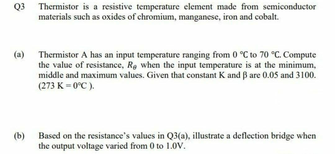
Thermistor is a resistive temperature element made from semiconductor materials such as oxides of chromium, manganese, iron and cobalt. Thermistor A has an input temperature ranging from 0 °C to 70 °C. Compute the value of resistance, Re when the input temperature is at the minimum, middle and maximum values. Given that constant K and B are 0.05 and 3100. (273 K = 0°C ). (a)
Q: IV) Explain the operating principle of a dual-slope ADC circuit, in your own words
A: ADC (ANALOG TO DIGITAL CONVERTER)- It converts analog signals to digital signals. ADC signals are of…
Q: Consider the circuit given below with R = 5k2 and Vcc = 12V. %3D The input signal is (Vs= 25 sin wt…
A: The circuit diagram is shown below, Where,R=5kΩVcc=12VIo=0.5mAVs=25sinωt mVVD=0.7V
Q: 30 Ω 40 Ω 20 Ω 10 Ω 80 N 60 N 50 Q bo Figure Q2(c)
A:
Q: A thermistor which has an input of a temperature change, the output form is:
A: The correct answer is OPTION B i.e Voltage
Q: Problem 3 In the circuit below, the diode behaves according to the constant 0.7-V drop model.…
A: Given: curve of Current Value of resistances Calculate: draw the graph of Output voltage
Q: 3) a) A GaAs diode with V1 = 4V C = 30 µF is given as the configuration on figure 10 V a) Obtain…
A: GIVEN DATA:
Q: 400 V is the input voltage given to a chopper, the required output is 650 V. The thyristor is…
A: DC-DC Converter: It will transfer the DC power from one circuit to another circuit at the required…
Q: Discuss the thermistor
A: Brief description: In the above given question we need to define about thermistors.
Q: 8. For the silicon diode circuit of Fig.P8, the input voltage (Vi) is a sinusoidal waveform. The…
A: The given circuit model is a half wave rectifier The formula for effective where we can calculate…
Q: 2. Derive an expression for Io in terms of IREF and B. Asssume that VA= c0 IREF O
A:
Q: A single phase bridge rectifier supplied from a 120V - 50 Hz sinusoidal source is connected to an…
A:
Q: 1. A 200 cm? PV cell has a reverse saturation current of 4.0x10⁻¹¹ A, and a short circuit current of…
A: Given information about a PV cell is Reverse saturation current I0=4×10-11 A. Short circuit current…
Q: Outline a method for solving a circuit that contains a single nonlinear element plus resistors, dc…
A: To explain the method for solving a circuit that contains a single non-linear element with resistors…
Q: The base-biased circuit in the figure is subjected to an increase in junction temperature from 25°C…
A: Common Emitter Amplifier Base Biasing. With the self-biasing of the emitter-bias circuit, one or…
Q: Intrinsic semiconductor material is characterized by a valence shell of how many electrons? Select…
A: Intrinsic semiconductor material means pure semiconductor it has not added doping material.…
Q: A DC voltage is required to power a load that can be modeled as a simple resistor with R = 500 Ω. A…
A: Given: A DC voltage is required to power a load that can be modeled as a simple resistor with R =…
Q: 2. A 10mm diameter hole is to be drilled in a 5mm HSS plate by EDM using RC circuit. The required…
A: 2. Electro Discharge Machining (EDM) is associate with electro-warm non-conventional machining live,…
Q: V, Consider the peak detector circuit on the right. The input v, is 5V for t=0. Determine the…
A: Given: Brief description: In the above given question they have mentioned an electrical circuit…
Q: In a temperature measurement system ,the element A receives the temperature value and produces…
A: Element A is a temperature measurement sensor, it is a thermocouple. The thermocouple is a device…
Q: Q9. Draw Zener regulator circuit to obtain regulated DC voltage 6.8 V. Considering input DC voltage…
A:
Q: d) Design the circuit of a voltage supply comprised of a full-wave bridge rectifier, capacitor…
A: It is asked to design a circuit of a voltage supply comprised of a full-wave bridge rectifier,…
Q: Please explain it briefly in detail.
A:
Q: + Vi 2 K D₁ 2.6 V D₂ A 1 K M + Vo I
A: Diode: It is a semiconductor device that is on in the forward bias condition and off in the reverse…
Q: Answer ALL parts (8) Consider the circuit in Figure A4. (a) Explain its operation with the aid of…
A: Given the circuit, as shown below: a) We need to explain its operation with the aid of diagrams.b)…
Q: Q3. A relaxation oscillator is to generate train of pulses that is used to fire a Thyristor circuit…
A:
Q: Q3. A relaxation oscillator is to generate train of pulses that is used to fire a Thyristor circuit…
A:
Q: A silicon pn junction employs NA = 2 x 1016 cm-3 and Np = 4 x 1016 cm-3. Determine the built-in…
A: The built-in potential for a pn junction can be expressed as Vbi=kTelnNANDni2 V--->(1) where…
Q: 4. For a silicon linearly graded junction with an impurity gradient of 5 x 10'/cm“, (a) calculate…
A: Depletion-width: It is the width of the depletion region. In the region the flow the charges…
Q: 6) You work as an engineer in a company and you have been given the assignment of measuring the…
A: We need calculate conductivity at both temperature, and energy band gap .
Q: When a switch is closed in a cirvuit containing a battery E,a resistance R and an inductance L,the…
A: As we have given: Ldidt+Ri=Edidt+RiL=EL ...1didt+pi=Q comparing with equation 1 we…
Q: Q.5 (a) Referring to the circuit in Figure B.3, diode, Di is Silicone with VD = 0.7V. UTM S UTM S…
A: In this question, Half wave Rectifier is given Find the all unkown parameters and draw the output…
Q: e. In terms of charge and current, what is the meaning of the time constant t in a charging RC…
A: The explanation is as follows.
Q: Electronics Circuit: BJT biasing A Voltage Divider bias NPN BJT (Beta = 80) circuit is connected to…
A:
Q: Q. Give the state-table of the following state diagram. 1/0 A 0 /0 В 0/0 1/0 1/0 1/0 0/0 0/1 D State…
A: The given circuit diagram is:
Q: a) Draw the energy band diagram of a MOSFET transistor, when -5 volts are applied to the drain…
A: a) We need to draw a band diagram of a MOSFET transistor, 5 Voltage are applied to drain contact. b)…
Q: A single phase bridge type full wave uncontrolled rectifier is connected to a voltage source and has…
A: Rectifier: It is a device which converts AC signal to DC signal with the help of uncontrolled or…
Q: 2000 2000 200 Vs Figure Q3(a)
A: Given: Brief description: In the above given system they want to know the transfer function of the…
Q: A PMMC instrument with FSD of 100 µA and a coil resistance of 1 kQ is to be converted into a…
A:
Q: Consider a p-n junction at 25 C with a reverse saturation current 10^-9 A. Calculate the voltage…
A: Although formula for diode current is given by ID=Ise38.9Vd-1where,Is=saturation currentVd=diode…
Q: esign a battery charger for safe operation in a damp garage environment to use for charging your…
A: Input voltage, Vrms=110VInput voltage is alternating voltageTransformation…
Q: Which of the following is true about a practical battery ? O A. It can be modelled as an ideal…
A: Practical battery can be modelled as an ideal battery with a small resistance connected in series.
Q: 2) Consider the circuit shown below. 10 V -10 V Assume Va has the ideal waveform shown in the…
A: (a) The figure given is a differential amplifier. The output voltage of the differential amplifier…
Q: Q 3/ We measured the current that appeared on the drawn screen as shown in the figure by using three…
A: Here,the three different current gauges are connected in series and they are, 1. De-Arsenval type 2.…
Q: Consider the peak detector circuit on the right. The input v, is 5V for t=0. Determine the…
A: According to the question, for the circuit shown below we need to find
Q: 1. A tunnel diode can be connected to a microwave circulator to make a negative resistance…
A: Tunnel diodes are microwave and millimeter-wave semiconductor diodes that are utilized in microwave…
Q: 3C) Calculate the values of the second harmonic (HD2) and third (HD3) as well as Aup3for each of the…
A: G(t)=α1xt+α3xt3H(t)=β
Q: 4. A diode circuit is proposed in circuit 4.1 below. Assuming that the diodes are semi-normal with a…
A:
Q: A certain non-linear device has the following output current expression: + V1 11 Answer: Non Linear…
A: SOLUTION Given--> TWO PORT NETWORK I2…
Trending now
This is a popular solution!
Step by step
Solved in 2 steps with 4 images
- Outline a method for solving a circuit that contains a single nonlinear element plus resistors, dc voltage sources, and dc current sources, given the volt–ampere characteristic of the nonlinear device.What type of device is shown in the attached figure, if the waveforms illustrated are present at its CK and Q terminals? State 5 applications using the answer in 1.For the ideal-diode clipper circuit given below, VS = 12.sinωt V. Determine the output voltage Vout and sketch this function. Remove the short circuit between points x and y, and replace it with a 2kΩ Resistor. Find the range of values of VS for; D1 and D2 are OFF D1 is ON and D2 is OFF D1 is OFF and D2 is ON Is it possible for both D1 and D2 to be ON?
- For the attenuator circuit shown, assume C1 and C2 to be very large (∞) capacitors. Don’t be thrown off by the capacitors (How do they behave at DC? How do they behave at AC if C =∞). Assume D1 and D2 are identical diodes with n=1, V T = 25 mV (use the exponential model). a. Determine the value of the dc voltage, V_N when I = 1mA. b. Draw the small-signal equivalent circuit, replacing the diodes with their small signal resistive model, r_d. c. Determine the value of V_o/V_s when I = 1mA.design a battery charger for safe operation in a damp garage environment to use for charging your 12 VDC car battery. Design specifications include: (a) Input is a 110rms VAC. (VP=110x ) at 60 Hz from a three wire service that meets the National Electrical Code. (b) Output is a nominal 12 volts VDC at the cathode of the diode. (c) Specify a resistor, R, to limit the maximum battery charging current to 10 amperes into the 12 volt car battery assuming the battery is completely dead (0 volts) when you first connect the charger. (d) There is no ripple voltage design specification. Explain why this is unnecessary in this application. (e) The battery charger case is metal. (f) Assume a diode with VF = 0.7 V (g) The fuse in the primary circuit is to protect the power supply from a short-circuit at the battery terminals either from total battery failure or accidentally short circuiting the charging cable to ground…1-) Ideal Envelope Detector2-) AM demodulation using diode and RLC circuit3-) Demodulation of AM signal using envelope detectorQuestion 9: compare the above demodulation techniques in terms of pros and cons. Which one should be used in practical application and why? Explain.
- Given the following details: The inverting adder schematic as seen below Vac is an AC voltage source which generates a sine waveform with amplitude 1mV and frequency 1kHz Vout is a sine waveform with amplitude 1V and has a DC offset of 3.5V Find the values of Vdc, R1, R2 and Rf that would satisfy the description for Vout. Assume ideal scenario (i.e. do theoretical computations instead of practical simulations)Surface barrier diodes have a lower noise figure in high frequencies True False The capacitance of the Varactor diode increases with an increase in reverse bias voltage True False The dark current is a current that will exist with no applied illumination True False The lifetime of LCDs is longer than that of LEDs True False The liquid-crystal display (LCD) has the distinct advantage of having a lower power requirement than the LED (light emitting diodes) True FalseQ 3 Bring out the advantages and disadvantages of microwave tube devices andsemiconductor devices.What are the most common types of microwave diodes and transistors in use give theirbasic features features and applications?What are the most common types of microwave ICs? Give details of the circuit elementsand applications
- i) The equation above contains really only three variables in it: Id, Vd, and T. All the other terms are constants. Since in most cases we assume temperature is fairly constant as well, we are really only dealing with two variables: diode current and diode voltage. Based on this realization, re-write the equation as proportionality rather than equality, showing how the two variables of diode current and voltage relate ii) Based on this simplified equation, what would an I vs V graph for a PN junction look like? How does this graph compare against the I vs V graph for a resistor? iii) When "P" and "N" type semiconductor pieces are brought into close contact, free electrons from the "N" piece will rush over to fill holes in the "P" piece, creating a zone on both sides of the contact region devoid of charge carriers. What is this zone called, and what are its electrical characteristics? iv) What happens to the thickness of the region in a PN junction (answer above) when an external…2. A certain zener diode has a maximum power rating of 300 mW at 40 deg Cand a derating factor of 1.4mW/deg C. Determine the maximum power the zener can dissipate at a temperature of 80 deg C. 3. From the datasheet, a 1N4728A zener diode has a ZZ of 10 0. The datasheet gives VZ = 3.3 V at a test current, IZ, of 76 mA. What is the voltage across the zener terminals when the current is 90 mA? When the current is 45 mA?A series RC circuit consisting of 50 ohms and 100 uF is energized by a 50 volts supply. What is the voltage in the resistor at time equal to 20 msec.? How large is the charge stored in the capacitor duringthis time ? If the supply is suddenly switch off how long will it take for the charge be halved ?