Q.5 (a) Referring to the circuit in Figure B.3, diode, Di is Silicone with VD = 0.7V. UTM S UTM S UTM V = 240 Vns 8 UTM S UTM D, f= 50 Hz 8 UTM UTM sec UTM UT UTM S UTM UTM d UTM S UTM S UTM UTM Figure B.3 BUTM UT 8 UTM UT) UTM SUTM S UTM UT UTM (ii) Calculate the average output voltage, Vodavg). aUTM UT I the o cycles. Make sure to label the x- and y- axis properly. (iv) Draw and label the output if a capacitor, C1, 100 µF connected parallel to Resistor, R1, 5002 in Figure B.3. (Hint: You must calculate the 8 UTM UTM & UTM ripple voltage peak-to-peak, V. (p-p) to get a proper output drawing). TM TM TM
Q.5 (a) Referring to the circuit in Figure B.3, diode, Di is Silicone with VD = 0.7V. UTM S UTM S UTM V = 240 Vns 8 UTM S UTM D, f= 50 Hz 8 UTM UTM sec UTM UT UTM S UTM UTM d UTM S UTM S UTM UTM Figure B.3 BUTM UT 8 UTM UT) UTM SUTM S UTM UT UTM (ii) Calculate the average output voltage, Vodavg). aUTM UT I the o cycles. Make sure to label the x- and y- axis properly. (iv) Draw and label the output if a capacitor, C1, 100 µF connected parallel to Resistor, R1, 5002 in Figure B.3. (Hint: You must calculate the 8 UTM UTM & UTM ripple voltage peak-to-peak, V. (p-p) to get a proper output drawing). TM TM TM

Introductory Circuit Analysis (13th Edition)
13th Edition
ISBN:9780133923605
Author:Robert L. Boylestad
Publisher:Robert L. Boylestad
Chapter1: Introduction
Section: Chapter Questions
Problem 1P: Visit your local library (at school or home) and describe the extent to which it provides literature...

Related questions
Question
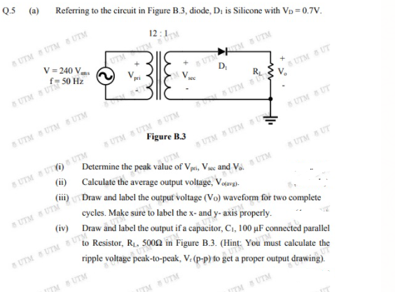
Transcribed Image Text:Q.5 (a) Referring to the circuit in Figure B.3, diode, Di is Silicone with VD = 0.7V.
UTM S UTM S UTM
V = 240 Vns
8 UTM S UTM
D,
f= 50 Hz
8 UTM UTM
sec
UTM UT
UTM S UTM UTM
d UTM
S UTM S UTM UTM
Figure B.3
BUTM UT
8 UTM UT) UTM
SUTM S UTM UT
UTM
(ii) Calculate the average output voltage, Vodavg).
a UTM UT
I the o
cycles. Make sure to label the x- and y- axis properly.
(iv) Draw and label the output if a capacitor, C1, 100 µF connected parallel
to Resistor, R1, 500n in Figure B.3. (Hint: You must calculate the
UTM UTM & UTM
ripple voltage peak-to-peak, V. (p-p) to get a proper output drawing).
ITM SUTM
TM S UTM
TM B UTM
Expert Solution
This question has been solved!
Explore an expertly crafted, step-by-step solution for a thorough understanding of key concepts.

Step by step
Solved in 2 steps with 1 images

Knowledge Booster


Learn more about
Need a deep-dive on the concept behind this application? Look no further. Learn more about this topic, electrical-engineering and related others by exploring similar questions and additional content below.Recommended textbooks for you
Introductory Circuit Analysis (13th Edition)
Electrical Engineering
ISBN:
9780133923605
Author:
Robert L. Boylestad
Publisher:
PEARSON

Delmar's Standard Textbook Of Electricity
Electrical Engineering
ISBN:
9781337900348
Author:
Stephen L. Herman
Publisher:
Cengage Learning

Programmable Logic Controllers
Electrical Engineering
ISBN:
9780073373843
Author:
Frank D. Petruzella
Publisher:
McGraw-Hill Education
Introductory Circuit Analysis (13th Edition)
Electrical Engineering
ISBN:
9780133923605
Author:
Robert L. Boylestad
Publisher:
PEARSON
Delmar's Standard Textbook Of Electricity
Electrical Engineering
ISBN:
9781337900348
Author:
Stephen L. Herman
Publisher:
Cengage Learning
Programmable Logic Controllers
Electrical Engineering
ISBN:
9780073373843
Author:
Frank D. Petruzella
Publisher:
McGraw-Hill Education

Fundamentals of Electric Circuits
Electrical Engineering
ISBN:
9780078028229
Author:
Charles K Alexander, Matthew Sadiku
Publisher:
McGraw-Hill Education

Electric Circuits. (11th Edition)
Electrical Engineering
ISBN:
9780134746968
Author:
James W. Nilsson, Susan Riedel
Publisher:
PEARSON

Engineering Electromagnetics
Electrical Engineering
ISBN:
9780078028151
Author:
Hayt, William H. (william Hart), Jr, BUCK, John A.
Publisher:
Mcgraw-hill Education,