Question 2 (ii) Now sketch the same logic circuit as for (ii) above but only use NAND gates to implement the logic. A truth table indicating the state of an output, Z, as it depends on three inputs A, B and Cis given below: B 1 1 1 1 1 1 1 1 1 1 1 1 () Write down the sum of products expression as represented by the truth table and then simplify this expression if possible. (iv) Show how you can also implement this logic using a generic 8:1 MUX instead of logic gates. (ii) Sketch the logic circuit that represent your simplified expression in (i) Is Is lo s.
Question 2 (ii) Now sketch the same logic circuit as for (ii) above but only use NAND gates to implement the logic. A truth table indicating the state of an output, Z, as it depends on three inputs A, B and Cis given below: B 1 1 1 1 1 1 1 1 1 1 1 1 () Write down the sum of products expression as represented by the truth table and then simplify this expression if possible. (iv) Show how you can also implement this logic using a generic 8:1 MUX instead of logic gates. (ii) Sketch the logic circuit that represent your simplified expression in (i) Is Is lo s.

Chapter22: Sequence Control
Section: Chapter Questions
Problem 6SQ: Draw a symbol for a solid-state logic element AND.

Related questions

Question
Just question (iii) and (iv) please
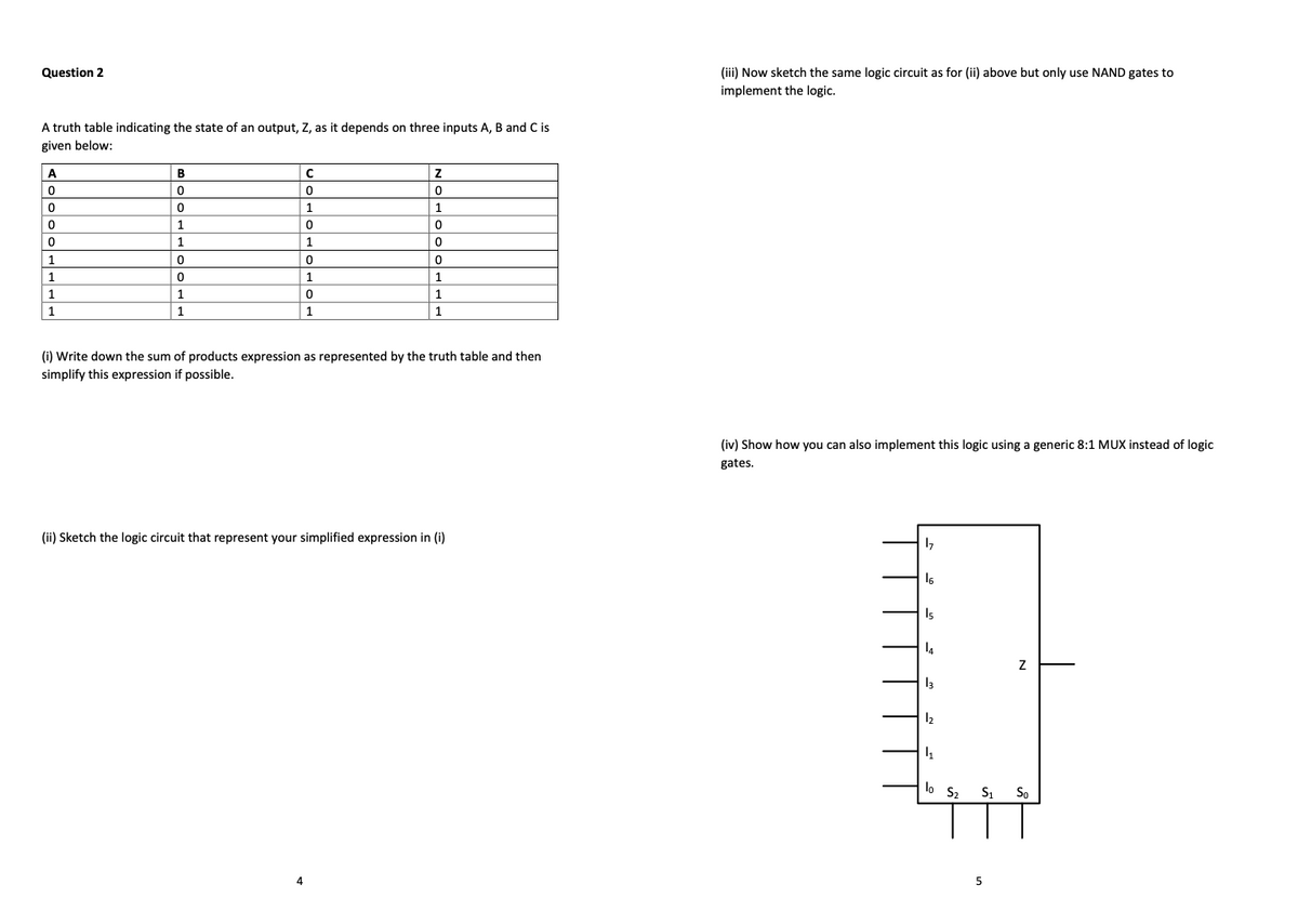
Transcribed Image Text:Question 2
(iii) Now sketch the same logic circuit as for (ii) above but only use NAND gates to
implement the logic.
A truth table indicating the state of an output, Z, as it depends on three inputs A, B and C is
given below:
A
B
1
1
1.
1.
1
1
1
1
1
1
1
1
(i) Write down the sum of products expression as represented by the truth table and then
simplify this expression if possible.
(iv) Show how you can also implement this logic using a generic 8:1 MUX instead of logic
gates.
(ii) Sketch the logic circuit that represent your simplified expression in (i)
Is
lo S2
So
4
5
Expert Solution
This question has been solved!
Explore an expertly crafted, step-by-step solution for a thorough understanding of key concepts.

Step by step
Solved in 3 steps with 2 images

Knowledge Booster


Learn more about
Need a deep-dive on the concept behind this application? Look no further. Learn more about this topic, electrical-engineering and related others by exploring similar questions and additional content below.Recommended textbooks for you