Questions 1 The operational amplifier (op-amp) in Figure 1 is an ideal op-amp with maximum output voltage, vo(max) is +12 V and the minimum output voltage, vo(min) is -12 V. A sine wave with +5V peak-to-peak voltage is applied as the input, vin as shown. R. RE Voltage (V) GND 10- Vin R2 Vin Vo Time 0.5 -5 -10- 1 1.5 (ms) GND Figure 1 For each of the following conditions, derive or explain the relationship between output voltage, vo and input voltage, Vin, and then draw the input and output voltage waveforms on same graph. Label the x-axis, y-axis, peak voltages and units. a) R1 = R2 = R3 = 10 kQ and RF = 3R1. b) R2 = R3 = 10 kn, RF = 3R2 and R1 is broken (open circuit). c) R1 = R2 = R3 = 1O kN and Re is broken (open circuit). d) R; = R2 = 10 kQ, RF = 3R1, R3 is broken (open circuit) and the op-amp's inverting and non-inverting terminals are accidently interchanged where node 'x' is connected to the non-inverting input while node y' is connected to the inverting input of the op-amp.
Questions 1 The operational amplifier (op-amp) in Figure 1 is an ideal op-amp with maximum output voltage, vo(max) is +12 V and the minimum output voltage, vo(min) is -12 V. A sine wave with +5V peak-to-peak voltage is applied as the input, vin as shown. R. RE Voltage (V) GND 10- Vin R2 Vin Vo Time 0.5 -5 -10- 1 1.5 (ms) GND Figure 1 For each of the following conditions, derive or explain the relationship between output voltage, vo and input voltage, Vin, and then draw the input and output voltage waveforms on same graph. Label the x-axis, y-axis, peak voltages and units. a) R1 = R2 = R3 = 10 kQ and RF = 3R1. b) R2 = R3 = 10 kn, RF = 3R2 and R1 is broken (open circuit). c) R1 = R2 = R3 = 1O kN and Re is broken (open circuit). d) R; = R2 = 10 kQ, RF = 3R1, R3 is broken (open circuit) and the op-amp's inverting and non-inverting terminals are accidently interchanged where node 'x' is connected to the non-inverting input while node y' is connected to the inverting input of the op-amp.

Power System Analysis and Design (MindTap Course List)
6th Edition
ISBN:9781305632134
Author:J. Duncan Glover, Thomas Overbye, Mulukutla S. Sarma
Publisher:J. Duncan Glover, Thomas Overbye, Mulukutla S. Sarma
Chapter12: Power System Controls
Section: Chapter Questions
Problem 12.3P

Related questions
Question
Transcribed Image Text:Questions 1
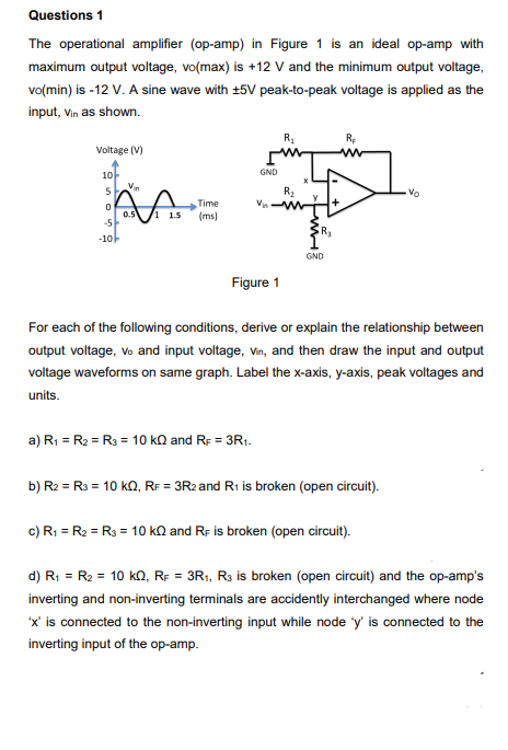
The operational amplifier (op-amp) in Figure 1 is an ideal op-amp with
maximum output voltage, vo(max) is +12 V and the minimum output voltage,
vo(min) is -12 V. A sine wave with +5V peak-to-peak voltage is applied as the
input, vin as shown.
R.
RE
Voltage (V)
GND
10-
Vin
R2
Vin
Vo
Time
0.5
-5
-10-
1 1.5
(ms)
GND
Figure 1
For each of the following conditions, derive or explain the relationship between
output voltage, vo and input voltage, Vin, and then draw the input and output
voltage waveforms on same graph. Label the x-axis, y-axis, peak voltages and
units.
a) R1 = R2 = R3 = 10 kQ and RF = 3R1.
b) R2 = R3 = 10 kn, RF = 3R2 and R1 is broken (open circuit).
c) R1 = R2 = R3 = 1O kN and Re is broken (open circuit).
d) R; = R2 = 10 kQ, RF = 3R1, R3 is broken (open circuit) and the op-amp's
inverting and non-inverting terminals are accidently interchanged where node
'x' is connected to the non-inverting input while node 'y' is connected to the
inverting input of the op-amp.
Expert Solution
This question has been solved!
Explore an expertly crafted, step-by-step solution for a thorough understanding of key concepts.

Step by step
Solved in 4 steps with 4 images

Knowledge Booster


Learn more about
Need a deep-dive on the concept behind this application? Look no further. Learn more about this topic, electrical-engineering and related others by exploring similar questions and additional content below.Recommended textbooks for you
Power System Analysis and Design (MindTap Course …
Electrical Engineering
ISBN:
9781305632134
Author:
J. Duncan Glover, Thomas Overbye, Mulukutla S. Sarma
Publisher:
Cengage Learning
Power System Analysis and Design (MindTap Course …
Electrical Engineering
ISBN:
9781305632134
Author:
J. Duncan Glover, Thomas Overbye, Mulukutla S. Sarma
Publisher:
Cengage Learning