Questions: 1. For the circuit of Figure (1), the voltage gain from base to colector is approximately: (a)l (b)12 (c)112 (d)224 2. The output signal of the common-emitter amplifier is out-of-phase with the input by: (a)0° (b)45° (c)90°: (d) 180°. 3. If the emitter bypass capacitor in Figure (1) is removed, the Amplifier voltage gain will:
Questions: 1. For the circuit of Figure (1), the voltage gain from base to colector is approximately: (a)l (b)12 (c)112 (d)224 2. The output signal of the common-emitter amplifier is out-of-phase with the input by: (a)0° (b)45° (c)90°: (d) 180°. 3. If the emitter bypass capacitor in Figure (1) is removed, the Amplifier voltage gain will:

Chapter25: Television, Telephone, And Low-voltage Signal Systems
Section25.1: Television Circuit
Problem 5R: From a cost standpoint, which system is more economical to install: a master amplifier distribution...

Related questions

Question
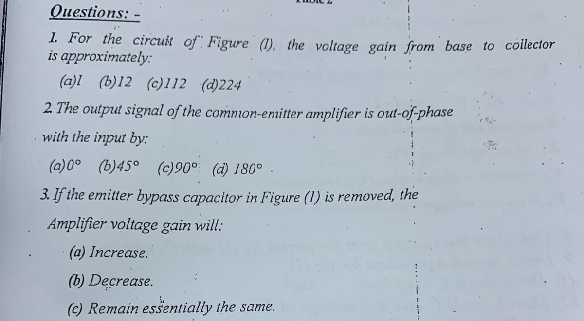
Transcribed Image Text:Questions: -
1. For the circuit of Figure (1), the voltage gain from base to collector
is approximately:
(a)l (b)12 (c)112 (d)224
2 The output signal of the common-emitter amplifier is out-of-phase
with the input by:
(a)0° (b)45° (c)90°: (d) 180°.
3. If the emitter bypass capacitor in Figure (1) is removed, the
mplifier voltage gain will:
(a) Increase.
(b) Decrease.
(c) Remain essentially the same.
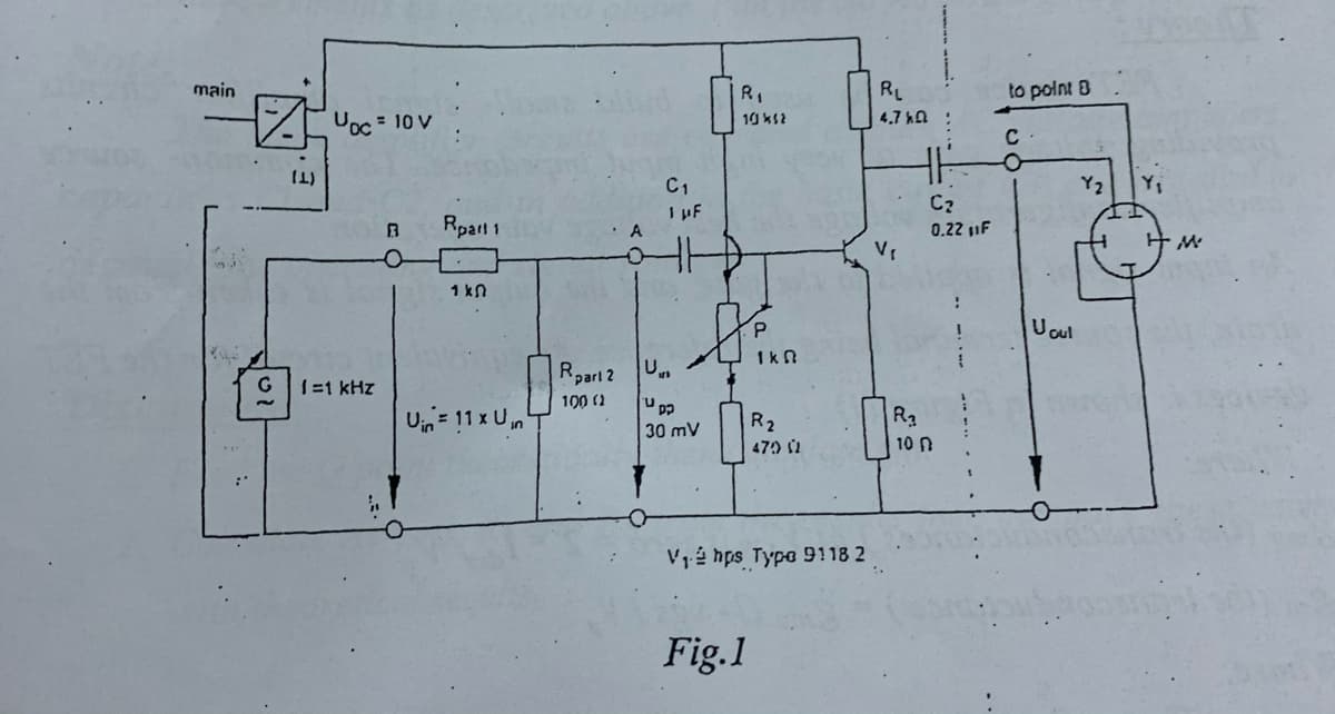
Transcribed Image Text:main
R,
RL
to polnt 8
Uoc = 10 V
4.7 kA
10 ks2
C1
I pF
Y2
Yi
Rparl 1
• A
0.22 1F
1 kn
Uoul
1k n
Rparl 2
1=1 kHz
100 (2
Uin= 11 x Un
R2
R2
47 2
30 mV
10 n
Vé hps Typo 9118 2
Fig.1
Expert Solution
This question has been solved!
Explore an expertly crafted, step-by-step solution for a thorough understanding of key concepts.

Step by step
Solved in 4 steps

Knowledge Booster


Learn more about
Need a deep-dive on the concept behind this application? Look no further. Learn more about this topic, electrical-engineering and related others by exploring similar questions and additional content below.Recommended textbooks for you
EBK ELECTRICAL WIRING RESIDENTIAL
Electrical Engineering
ISBN:
9781337516549
Author:
Simmons
Publisher:
CENGAGE LEARNING - CONSIGNMENT
EBK ELECTRICAL WIRING RESIDENTIAL
Electrical Engineering
ISBN:
9781337516549
Author:
Simmons
Publisher:
CENGAGE LEARNING - CONSIGNMENT