roblem 6: Use element matrices potential energy formulations to solve the beam problem shown in Figure.5. dal displacement values. Make sure to construct the grid information table and one-dimensional elements e/mesh with appropriate labeling, numbering and displacement, loads nodal points.
roblem 6: Use element matrices potential energy formulations to solve the beam problem shown in Figure.5. dal displacement values. Make sure to construct the grid information table and one-dimensional elements e/mesh with appropriate labeling, numbering and displacement, loads nodal points.

Mechanics of Materials (MindTap Course List)
9th Edition
ISBN:9781337093347
Author:Barry J. Goodno, James M. Gere
Publisher:Barry J. Goodno, James M. Gere
Chapter10: Statically Indeterminate Beams
Section: Chapter Questions
Problem 10.4.2P: A fixed-end beam AB carries point load P acting at point C. The beam has a rectangular cross section...

Related questions
Question
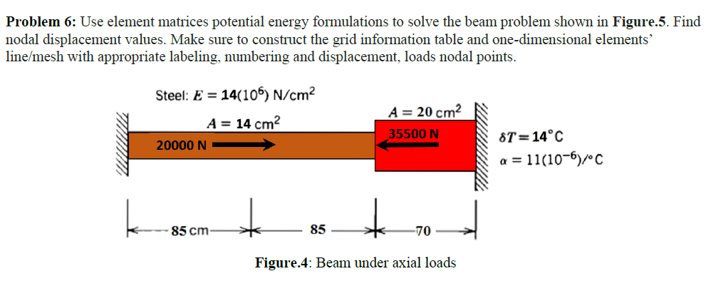
Transcribed Image Text:Problem 6: Use element matrices potential energy formulations to solve the beam problem shown in Figure.5. Find
nodal displacement values. Make sure to construct the grid information table and one-dimensional elements'
line/mesh with appropriate labeling, numbering and displacement, loads nodal points.
Steel: E = 14(105) N/cm²
A = 20 cm?
A = 14 cm?
35500 N
ST=14°C
20000 N
a = 11(10-6)/C
85 cm
85
-70
Figure.4: Beam under axial loads
Expert Solution
This question has been solved!
Explore an expertly crafted, step-by-step solution for a thorough understanding of key concepts.

Step by step
Solved in 4 steps

Knowledge Booster


Learn more about
Need a deep-dive on the concept behind this application? Look no further. Learn more about this topic, mechanical-engineering and related others by exploring similar questions and additional content below.Recommended textbooks for you
Mechanics of Materials (MindTap Course List)
Mechanical Engineering
ISBN:
9781337093347
Author:
Barry J. Goodno, James M. Gere
Publisher:
Cengage Learning
Mechanics of Materials (MindTap Course List)
Mechanical Engineering
ISBN:
9781337093347
Author:
Barry J. Goodno, James M. Gere
Publisher:
Cengage Learning