See the drive belt profile below. If at any given time the Beit circumference of its pulley, determine the contact are between the belt and the pulley if rl 0.505 in degrees and r2 = 2.3 in
See the drive belt profile below. If at any given time the Beit circumference of its pulley, determine the contact are between the belt and the pulley if rl 0.505 in degrees and r2 = 2.3 in

International Edition---engineering Mechanics: Statics, 4th Edition
4th Edition
ISBN:9781305501607
Author:Andrew Pytel And Jaan Kiusalaas
Publisher:Andrew Pytel And Jaan Kiusalaas
Chapter8: Centroids And Distributed Loads
Section: Chapter Questions
Problem 8.73P

Related questions
Question
13
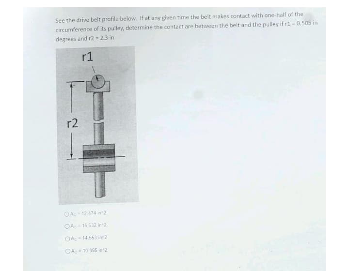
Transcribed Image Text:See the drive belt profile below. If at any given time the belt makes contact with one-half of the
circumference of its pulley, determine the contact are between the belt and the pulley if r1 = 0.505 in
degrees and r2 = 2.3 in
r1
r2
OAc = 12.474 in 2
OA:= 16 632 in 2
OA: = 14 553 in 2
OAc 10 395 in 2
Expert Solution
This question has been solved!
Explore an expertly crafted, step-by-step solution for a thorough understanding of key concepts.

Step by step
Solved in 2 steps with 2 images

Knowledge Booster


Learn more about
Need a deep-dive on the concept behind this application? Look no further. Learn more about this topic, mechanical-engineering and related others by exploring similar questions and additional content below.Recommended textbooks for you
International Edition---engineering Mechanics: St…
Mechanical Engineering
ISBN:
9781305501607
Author:
Andrew Pytel And Jaan Kiusalaas
Publisher:
CENGAGE L

Mechanics of Materials (MindTap Course List)
Mechanical Engineering
ISBN:
9781337093347
Author:
Barry J. Goodno, James M. Gere
Publisher:
Cengage Learning
International Edition---engineering Mechanics: St…
Mechanical Engineering
ISBN:
9781305501607
Author:
Andrew Pytel And Jaan Kiusalaas
Publisher:
CENGAGE L
Mechanics of Materials (MindTap Course List)
Mechanical Engineering
ISBN:
9781337093347
Author:
Barry J. Goodno, James M. Gere
Publisher:
Cengage Learning