Sign (L, x L) Resultant of wind pressure Pipe column D Overturning moment -B about x axis FH F at each 4 bolt at each 4 bolt (a) Рipe columa W FH = Rh One half of over turning moment about x axis acts on each bolt pair Base plate (p) F14- Footing Tension TR RCompression (b) FH FH -b=D12 in. -h 14in. R+ R- R- (c)

Structural Analysis
6th Edition
ISBN:9781337630931
Author:KASSIMALI, Aslam.
Publisher:KASSIMALI, Aslam.
Chapter2: Loads On Structures
Section: Chapter Questions
Problem 1P
icon
Related questions
Question

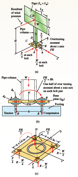
A sign of weight W is supported at its base by four bolts anchored in a concrete footing. Wind pressure p acts normal to the surface of the sign; the resultant of the uniform wind pressure is force F at the center
of pressure (C.P.). The wind force is assumed to create equal shear forces F/4 in the y direction at each bolt (see figure parts a and c). The overturning effect of the wind force also causes an uplift force R at bolts A and C and a downward force (-R) at bolts B and D (see figure part b). The resulting effects of the wind and the associated ultimate stresses for each stress condition are normal stress in each bolt (σu = 60 ksi); shear through the base plate (τu = 17 ksi); horizontal shear and bearing on each bolt (τhu = 25 ksi and σbu = 75 ksi); and bearing on the bottom washer at B (or D) (σbw = 50 ksi). Find the maximum wind pressure pmax (psf) that can
be carried by the bolted support system for the sign if a safety factor of 2.5 is desired with respect to the ultimate wind load that can be carried.
Use the following numerical data: bolt 3 in. db = 4 ; washer dw = 1.5 in.; base plate tbp = 1 in.; base plate dimensions h = 14 in. and b = 12 in.; W = 500 lb; H =17 ft; sign dimensions Lv = 10 ft. XLh = 12 ft.; pipe column diameter d = 6 in.; and pipe column thickness t = 3/8 in.

Sign (L, x L)
Resultant
of wind
pressure
Pipe
column
D
Overturning
moment
-B about x axis
FH
F
at each
4
bolt
at each
4
bolt
(a)
Рipe columa
W
FH
= Rh
One half of over turning
moment about x axis acts
on each bolt pair
Base
plate (p)
F14-
Footing
Tension TR
RCompression
(b)
FH
FH
-b=D12 in.
-h 14in.
R+
R-
R-
(c)
Transcribed Image Text:Sign (L, x L) Resultant of wind pressure Pipe column D Overturning moment -B about x axis FH F at each 4 bolt at each 4 bolt (a) Рipe columa W FH = Rh One half of over turning moment about x axis acts on each bolt pair Base plate (p) F14- Footing Tension TR RCompression (b) FH FH -b=D12 in. -h 14in. R+ R- R- (c)
Expert Solution
trending now

Trending now

This is a popular solution!

steps

Step by step

Solved in 9 steps

Blurred answer
Knowledge Booster
Plane and space trusses
Learn more about
Need a deep-dive on the concept behind this application? Look no further. Learn more about this topic, civil-engineering and related others by exploring similar questions and additional content below.
Recommended textbooks for you
Structural Analysis
Structural Analysis
Civil Engineering
ISBN:
9781337630931
Author:
KASSIMALI, Aslam.
Publisher:
Cengage,
Structural Analysis (10th Edition)
Civil Engineering
ISBN:
9780134610672
Author:
Russell C. Hibbeler
Publisher:
PEARSON
Principles of Foundation Engineering (MindTap Cou…
Civil Engineering
ISBN:
9781337705028
Author:
Braja M. Das, Nagaratnam Sivakugan
Publisher:
Cengage Learning
Fundamentals of Structural Analysis
Civil Engineering
ISBN:
9780073398006
Author:
Kenneth M. Leet Emeritus, Chia-Ming Uang, Joel Lanning
Publisher:
McGraw-Hill Education
Sustainable Energy
Sustainable Energy
Civil Engineering
ISBN:
9781337551663
Author:
DUNLAP, Richard A.
Publisher:
Cengage,
Traffic and Highway Engineering
Civil Engineering
ISBN:
9781305156241
Author:
Garber, Nicholas J.
Publisher:
Cengage Learning