T2 Vs R Vo AA chopper circuit in the figure, 400 V (rms) Control the power of an ohmic load from a 50 Hz source. . Since the load resistance is 20 0 and a = 30 °, a) The effective voltage, current and power of the load, b) Input power factor, c) Apparent, active and reactive powers drawn from the network,
T2 Vs R Vo AA chopper circuit in the figure, 400 V (rms) Control the power of an ohmic load from a 50 Hz source. . Since the load resistance is 20 0 and a = 30 °, a) The effective voltage, current and power of the load, b) Input power factor, c) Apparent, active and reactive powers drawn from the network,

Power System Analysis and Design (MindTap Course List)
6th Edition
ISBN:9781305632134
Author:J. Duncan Glover, Thomas Overbye, Mulukutla S. Sarma
Publisher:J. Duncan Glover, Thomas Overbye, Mulukutla S. Sarma
Chapter2: Fundamentals
Section: Chapter Questions
Problem 2.17P: Consider a load impedance of Z=jwL connected to a voltage and V let the current drawn be I. (a)...

Related questions
Question
Question-2
Can you throw the emergency solution?
I would appreciate it if you write legibly.
Transcribed Image Text:T1
iş
i.
T2
Vs
R
Vo
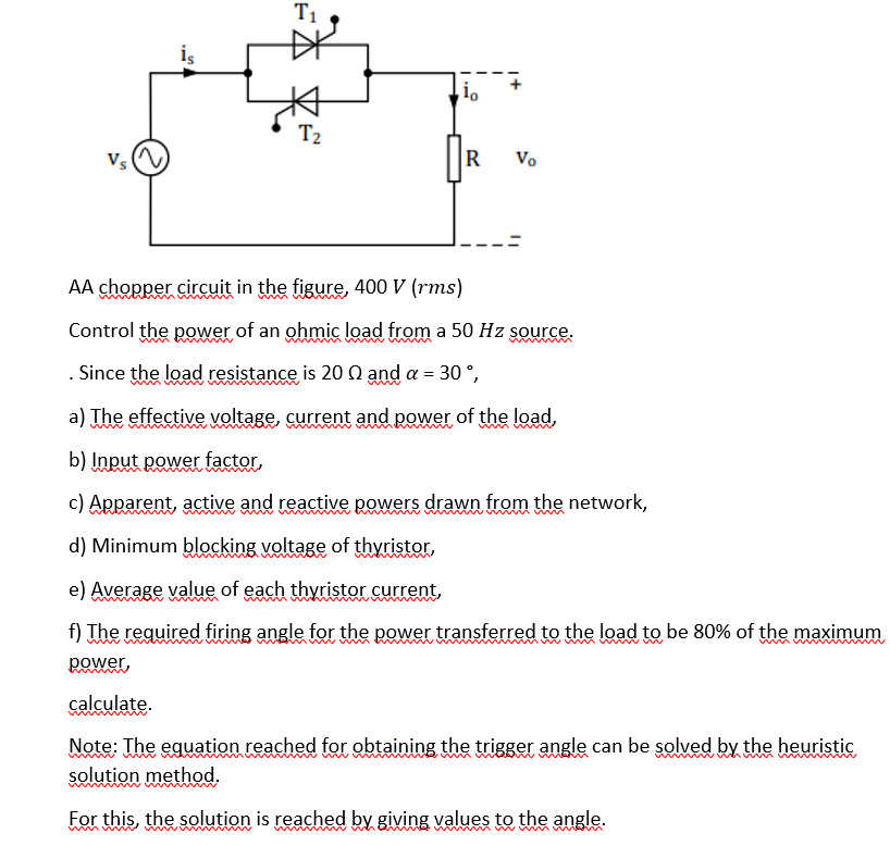
AA chopper circuit in the figure, 400 V (rms)
Control the power of an ohmic load from a 50 Hz source.
Since the load resistance is 20 Q and a = 30 °,
a) The effective voltage, current and power of the load,
b) Input power factor,
c) Apparent, active and reactive powers drawn from the network,
winw w
d) Minimum blocking voltage of thyristor,
e) Average value of each thyristor current,
f) The required firing angle for the power transferred to the load to be 80% of the maximum
power,
calculate.
Note: The equation reached for obtaining the trigger angle can be solved by the heuristic
solution method.
For this, the solution is reached by giving values to the angle.
mun m
Expert Solution
This question has been solved!
Explore an expertly crafted, step-by-step solution for a thorough understanding of key concepts.

Step by step
Solved in 3 steps with 1 images

Knowledge Booster


Learn more about
Need a deep-dive on the concept behind this application? Look no further. Learn more about this topic, electrical-engineering and related others by exploring similar questions and additional content below.Recommended textbooks for you
Power System Analysis and Design (MindTap Course …
Electrical Engineering
ISBN:
9781305632134
Author:
J. Duncan Glover, Thomas Overbye, Mulukutla S. Sarma
Publisher:
Cengage Learning
Power System Analysis and Design (MindTap Course …
Electrical Engineering
ISBN:
9781305632134
Author:
J. Duncan Glover, Thomas Overbye, Mulukutla S. Sarma
Publisher:
Cengage Learning