Task 1: Calculate and sketch the bending moment and shearing force diagrams for the horizontal beam shown below in Figure 1, which is simply supported at its ends. cL6 KN A 3m 2m Figure.l Consider the following in your answer: 1- Construct free-body diagram (FBD) to show the reactions forces, equivalent force of the distribution load. 2- Determine the required region of cuts and show the assumed internal shear force and bending moment on each cut in the beam. 3- Write the distribution functions of the shear force and bending moment for each cut in the beam. 4- By hand construct diagrams for the shear force and bending moment distributions. 5- Determine the values and positions of maximum shear forces and bending moment. 6- Justify the selection of standard rolled steel sections in mechanical designs.
Task 1: Calculate and sketch the bending moment and shearing force diagrams for the horizontal beam shown below in Figure 1, which is simply supported at its ends. cL6 KN A 3m 2m Figure.l Consider the following in your answer: 1- Construct free-body diagram (FBD) to show the reactions forces, equivalent force of the distribution load. 2- Determine the required region of cuts and show the assumed internal shear force and bending moment on each cut in the beam. 3- Write the distribution functions of the shear force and bending moment for each cut in the beam. 4- By hand construct diagrams for the shear force and bending moment distributions. 5- Determine the values and positions of maximum shear forces and bending moment. 6- Justify the selection of standard rolled steel sections in mechanical designs.

International Edition---engineering Mechanics: Statics, 4th Edition
4th Edition
ISBN:9781305501607
Author:Andrew Pytel And Jaan Kiusalaas
Publisher:Andrew Pytel And Jaan Kiusalaas
Chapter6: Beams And Cables
Section: Chapter Questions
Problem 6.42P: For the beam AB shown in Cases 1 and 2, derive and plot expressions for the shear force and bending...

Related questions
Question
Transcribed Image Text:Task 1:
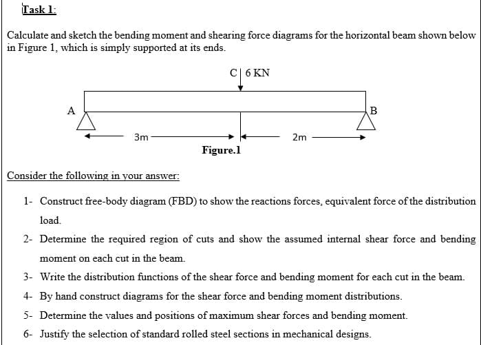
Calculate and sketch the bending moment and shearing force diagrams for the horizontal beam shown below
in Figure 1, which is simply supported at its ends.
cL6 KN
A
3m
2m
Figure.l
Consider the following in your answer:
1- Construct free-body diagram (FBD) to show the reactions forces, equivalent force of the distribution
load.
2- Determine the required region of cuts and show the assumed internal shear force and bending
moment on each cut in the beam.
3- Write the distribution functions of the shear force and bending moment for each cut in the beam.
4- By hand construct diagrams for the shear force and bending moment distributions.
5- Determine the values and positions of maximum shear forces and bending moment.
6- Justify the selection of standard rolled steel sections in mechanical designs.
Expert Solution
This question has been solved!
Explore an expertly crafted, step-by-step solution for a thorough understanding of key concepts.

This is a popular solution!

Trending now
This is a popular solution!

Step by step
Solved in 4 steps with 12 images

Recommended textbooks for you
International Edition---engineering Mechanics: St…
Mechanical Engineering
ISBN:
9781305501607
Author:
Andrew Pytel And Jaan Kiusalaas
Publisher:
CENGAGE L
International Edition---engineering Mechanics: St…
Mechanical Engineering
ISBN:
9781305501607
Author:
Andrew Pytel And Jaan Kiusalaas
Publisher:
CENGAGE L