For the beam shown in figure 2, (a) Draw the shear force and bending moment diagrams and determine maximum shear and bending moment in beam. Also find their locations. (b) Determine the maximum flexural stresses in beam
For the beam shown in figure 2, (a) Draw the shear force and bending moment diagrams and determine maximum shear and bending moment in beam. Also find their locations. (b) Determine the maximum flexural stresses in beam

Mechanics of Materials (MindTap Course List)
9th Edition
ISBN:9781337093347
Author:Barry J. Goodno, James M. Gere
Publisher:Barry J. Goodno, James M. Gere
Chapter5: Stresses In Beams (basic Topics)
Section: Chapter Questions
Problem 5.8.7P: A steel beam of length L = 16 in. and cross-sectional dimensions h = 0.6 in. and h = 2 in. (see...

Related questions
Question
please solve it completely and stepwisely
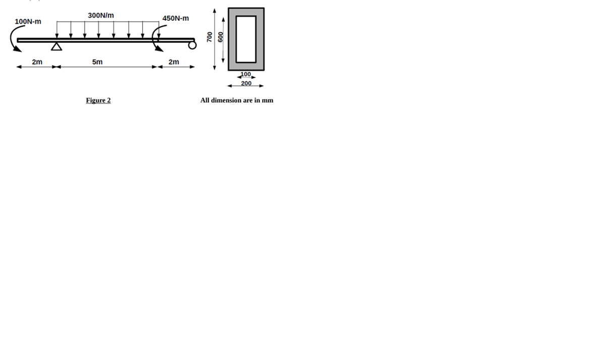
Transcribed Image Text:300N/m
450N-m
100N-m
2m
5m
2m
200
200
Figure 2
All dimension are in mm
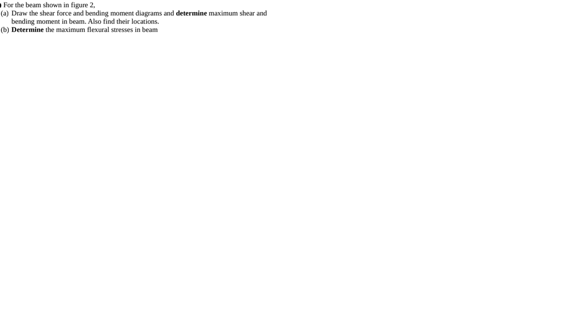
Transcribed Image Text:O For the beam shown in figure 2,
(a) Draw the shear force and bending moment diagrams and determine maximum shear and
bending moment in beam. Also find their locations.
(b) Determine the maximum flexural stresses in beam
Expert Solution
This question has been solved!
Explore an expertly crafted, step-by-step solution for a thorough understanding of key concepts.

Step by step
Solved in 6 steps with 2 images

Knowledge Booster


Learn more about
Need a deep-dive on the concept behind this application? Look no further. Learn more about this topic, mechanical-engineering and related others by exploring similar questions and additional content below.Recommended textbooks for you
Mechanics of Materials (MindTap Course List)
Mechanical Engineering
ISBN:
9781337093347
Author:
Barry J. Goodno, James M. Gere
Publisher:
Cengage Learning
Mechanics of Materials (MindTap Course List)
Mechanical Engineering
ISBN:
9781337093347
Author:
Barry J. Goodno, James M. Gere
Publisher:
Cengage Learning