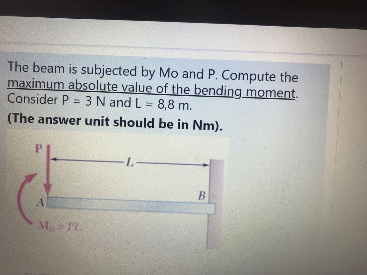
The beam is subjected by Mo and P. Compute the maximum absolute value of the bending moment. Consider P = 3 N and L = 8,8 m. (The answer unit should be in Nm). M PL


Q: For the beam shown below, compute the following: Assume El = 1 X 10 W = 300N/m 1.5m 0.5m 2 m R1 RZ
A: To Find : a) the mid span deflection Y b) the maximum deflection ymax Given : free body diagram…
Q: Solve,
A: Uniform distributed load is acting for the distance "4m".load P=(20 kN/m)×4m=80 kN ;this load will…
Q: The beam shown has an second moment of area of 9,500,000 mm4 and a controlling section modulus of…
A:
Q: Draw shear force digam and bending moment digram for the following beam 300 N 500 N 800 N to to 0.5…
A: A cantilever support will exert horizontal component of reaction, vertical component of reaction and…
Q: A beam is subjected to equal bending moments of Mz = 57 kip·ft. The cross-sectional dimensions are…
A: Firstly, we can split the beam into three rectangle cross-sections. As given in the figure, Area of…
Q: The steel beam has the cross- Wo section shown in the figure. Determine the largest possible…
A:
Q: Q2) Beam structure as shown above goes under internal moment of M = 5 kN m. Find (Omax)t and…
A:
Q: Draw Shear and Moment Diagrams for each of the beams below and find max bending stress. Every beam…
A:
Q: A beam of uniform rectangular cross-section is fixed at one end and carries an electric motor…
A: Given, Load on beam = W = 400 N Distance of load from support = L = 300 mm Maximum bending stress =…
Q: A simply supported beam of width 100 mm, height 200 mm and length 4 m is carrying a uniformly…
A:
Q: The steel beam has the cross section shown. The beam length is L= 19 ft, and the cross-sectional…
A:
Q: Determine the internal shear and moment acting at a section passing through point C n the beam shown…
A: Solution: Area of under the loading diagram gives the total load acting on the beam and the position…
Q: A beam with the cross-section shown is carrying a bending moment of M. Calculate the maximum bending…
A:
Q: Determine the absolute maximum normal stress (in unit of MPa) in the beam with external loadings…
A:
Q: The simply supported beam with following cross section is loaded with concentrated loads and uniform…
A:
Q: Determine the maximum bending stress and shear stress of the beam shown as shown in the figure.
A: Given beam with reactions at pin and roller support is shown below. As the load is uniform, both…
Q: If the beam is subjected to an internal moment of M = 2 kip # ft, determine the maximum tensile and…
A: Solution The cross-section is converted into four rectangles to find the moment of inertia about…
Q: ure. The bending moment at 0.5 m from the support is approximately
A: To determine the bending moment at 0.5 from support.
Q: For the beam and loading shown, draw the shear force and bending moment diagrams of the beam AC.…
A: The free-body diagram of the beam is given as, In this diagram, 2 kN load is displaced at point C…
Q: Maximum bending moment: A simply supported rectangular beam that is 3000 mm long supports a point…
A: Write the given data. P=5000 NL=3000 mmb=127 mmh=254 mmd=254 mm
Q: The beam shown below is carrying a vertical shear force v. TH Calculate the maximum shear stress (T)…
A:
Q: The magnitude of the bending moment acting on the circular cross section of a beam is M = 55,000 lb…
A: The bending stresses at D is 18055.22 psi.
Q: 180 lb/ft 4 in. LA B 8 in. 12 ft | 1200 1b
A: Given, b = 4 in d = 8 in To find maximum bending stress, we will need to find maximum bending…
Q: A beam is subjected to equal 14.3 kip-ft bending moments. Assume t₁ = t₂=tw 2 in., d = 14 in., b₁ =…
A: "Since you have posted a question with multiple subparts, we will solve the first three sub-parts…
Q: The steel beam has the cross section shown. The beam length is L = 17 ft, and the cross-sectional…
A:
Q: The steel beam has the cross section shown. The beam length is L= 18 ft, and the cross-sectional…
A:
Q: Substitute the value for s = 5 For the beam and loading shown. P = 20×S N, F = 10×S N, Q = 4xS N/m,…
A:
Q: of the beam are breadth, b = 35 mm and depth d = 125 mm. Calculate the maximum bending stress and…
A:
Q: 4 KN/m - 2 m 2 m 2 m
A: For this question we have to draw bending moment diagram and shear force diagram also. One…
Q: For the beam cross-section shown, (a) find the maximum bending stresses of the beam if the bending…
A:
Q: If Mz = 715 kip-ft, find the magnitude of the bending stress at a point H. For the beam cross…
A: Given data: Moment of Inertia = Iz = 60436 in4 Mz = 715 kip-ft The figure is missing in the data. By…
Q: A beam of uniform rectangular cross-section is fixed at one end and carries an electric motor…
A:
Q: For the beam shown below, determine the maximum bending stress in the beam. sketch the section…
A:
Q: Beam ABCDEFG below is subjected to multiple loads as show. The total length of the beam is 10m.…
A: according to given data
Q: H.W Draw shear force digam and bending moment digram for the following beam 300 N 500 N 800 N to 0.5…
A: Given: The load is 300 N, 500 N, and 800 N. The distance from point A is 0.5 m, 1.2 m, and 2 m.
Q: The beam shown has an second moment of area of 9,500,000 mm and a controlling section modulus of…
A: Maximum flexural stress due to bending is given by the following realation, Sigma,b=Mmax*Ymax/INA…
Q: Determine the maximum tensile and compressive bending stresses in the beam shown. Show: A.…
A: Answer: (a) The maximum tensile stress is 25 MPa. (b) The maximum compressive stress is 16.25 MPa.
Q: If the beam has a square cross section of 9 in on each side, QI determine the absolute maximum…
A: As per given question We have to determine maximum bending stress in beam
Q: 95Y For the beam loaded as shown find the location and the magnitude of the maximum tensilg bending…
A: Simply supported beam is hinged at both sides and load is applied in the middle anywhere,…
Q: Draw diagrams of shear force and bending moment for beam and loading shown. Calculate the maximum…
A: Given: The magnitude of udl, X = 407 N/m The length of beam BC, Y = 2.21 m The length of flange, Z =…
Q: is three times larger than in steel shaft. Q1) For the section shown aside, if the bending stress at…
A:
Q: Since beam M in the figure is under simple bending moment, A, B and C Calculate the bending stress…
A: Given data: Table and figure as shown above To determine: Bending stress and shear stress value at…
Q: An overhanging beam is loaded as indicated. In order to accommodate communication cables to be…
A: ◆ Determine the reactions at the support A and B using the equilibrium equations and draw the shear…
Q: If Mz = 200 kip-ft, find the magnitude of the bending stress at a point H. For the beam cross…
A:
Q: The cross-sectional dimensions of a beam are shown. Assume b-3 in., tetw-0.4375 in. and d-3.375 in.…
A:
Q: Find the bending stress at point B located at 0.7 m from the left end of the beam. 25 N 6 N/m B 3…
A: Given, UVL = 3 N/m to 6 N/m P = 25 N
Q: Q1: For the square beam shown below, the cross section area is 100 in', a) Find the shear force and…
A: Given dataArea of square cross section A = 100in2Side length a = 10inModulus of elasticity E =…

Step by step
Solved in 2 steps with 2 images


- .20 Determine the plastic moment Mpfor beam having the cross section shown in the figure ey=210 MPa.A rectangular beam with semicircular notches, as shown in part b of the figure, has dimensions h = 120 mm and h1= 100 mm. The maximum allowable bending stress in the plastic beam is emix = 6 M Pa, and the bending moment is M = 150 N · m. Determine the minimum permissible width bminof the beam.The hollow box beam shown in the figure is subjected to a bending moment M of such magnitude that the flanges yield but the webs remain linearly elastic. (a) Calculate the magnitude of the moment M if the dimensions of the cross section are A = 15 in., A] = 12.75 in., h = 9 in., and ey =7.5 in. Also, the yield stress is eY = 33 ksi. (b) What percent of the moment M is produced by the elastic core?
- A beam supporting a uniform load of intensity q throughout its length rests on pistons at points A, C and B (sec figure). The cylinders are filled with oil and are connected by a tube so that the oil pressure on each piston is the same. The pistons at A and B have diameter d1and the piston at C has diameter D2. (a) Determine the ratio of d2to d1so that the largest bending moment in the beam is as small as possible. Under these optimum conditions, what is the largest bending moment Mmaxin the beam? What is the difference in elevation between point C and the end supports?A C 200 x 17.1 channel section has an angle with equal legs attached as shown; the angle serves as a lintel beam. The combined steel section is subjected to a bending moment M having its vector directed along the z axis, as shown in the figure. The cent roi d C of the combined section is located at distances xtand ycfrom the centroid (C1) of the channel alone. Principal axes yl and yvare also shown in the figure and properties Ix1,Iy1and 0pare given. Find the orientation of the neutral axis and calculate the maximum tensile stress exand maximum compressive stress if the angle is an L 76 x 76 x 6.4 section and M = 3.5 kN - m. Use the following properties for principal axes for the combined section:/^, = 18.49 X 10⁶ nrai4,/;| = 1.602 X 106 mm4, ep= 7.448*(CW),_r£ = 10.70 mm,andvf= 24.07 mm.Determine the plastic modulus Z and shape factor/for a W 12 x 14 wide-flange beam. Obtain the cross-sectional dimensions and section modulus of the beam from Table F-l(a) in Appendix F.
- A cant i levé r b ea m i s supported by a tie rod at B as shown. Both the tie rod and the beam are steel with E = 30 x 106 psi. The tie rod is just taut before the distributed load q = 200 lb/ft is applied. Find the tension force in the tie rod. Draw shear-force and bending-moment diagrams for the beam, labeling all critical ordinates.A rectangular beam with notches and a hole (see figure) has dimensions h = 5.5 in., h1= 5 in., and width b = 1.6 in. The beam is subjected to a bending moment M = 130 kip-in., and the maximum allowable bending stress in the material (steel) is emax = 42,000 psi. What is the smallest radius Rminthat should be used in the notches? What is the diameter dmixof the largest hole that should be drilled at the mid height of the beam?A beam rests on supports at A and B and is loaded by a distributed load with intensity q as shown. A small gap exists between the unloaded beam and the support at C. Assume that span length L = 40 in. and flexural rigidity of the beam EI = 04 x 109lb-in2. Plot a graph of the bending moment at B as a function of the load intensity q. Hint: See Example 9-9 for guidance on computing the deflection at C.
- Determine the fixed-end moments (MAand MB) and fixed-end forces (R4and Rs) for a beam of length L supporting a triangular load of maximum intensity q0(see figure). Then draw the shear-force and bending-moment diagrams, labeling all critical ordinates.A simple beam ACE is constructed with square cross sections and a double taper (see figure). The depth of the beam at the supports is dAand at the midpoint is dc= 2d 4. Each half of the beam has length L. Thus, the depth and moment of inertia / at distance x from the left-hand end are, respectively, in which IAis the moment of inertia at end A of the beam. (These equations are valid for .x between 0 and L, that is, for the left-hand half of the beam.) Obtain equations for the slope and deflection of the left-hand half of the beam due to the uniform load. From the equations in part (a), obtain formulas for the angle of rotation 94at support A and the deflection Scat the midpoint.A beam ABC is fixed at end A and supported by beam DE at point B (sec figure). Both beams have the same cross section and are made of the same material. Determine all reactions due to the load P. What is the numerically largest bending moment in cither beam?