The beam with its section, given in the figure; a) Calculate the value of the location of the maximum tensile and shear stresses to occur alone b) Prime stresses you will calculate in the stress element to be taken around the neck point (E) and, Is the beam safe according to the shear stress? (0) check = 2315 N / cm2, temn = 1375 N / cm2 %3D
The beam with its section, given in the figure; a) Calculate the value of the location of the maximum tensile and shear stresses to occur alone b) Prime stresses you will calculate in the stress element to be taken around the neck point (E) and, Is the beam safe according to the shear stress? (0) check = 2315 N / cm2, temn = 1375 N / cm2 %3D

Mechanics of Materials (MindTap Course List)
9th Edition
ISBN:9781337093347
Author:Barry J. Goodno, James M. Gere
Publisher:Barry J. Goodno, James M. Gere
Chapter6: Stresses In Beams (advanced Topics)
Section: Chapter Questions
Problem 6.8.3P: A beam of wide-flange shape, W 8 x 28, has the cross section shown in the figure. The dimensions are...

Related questions
Question
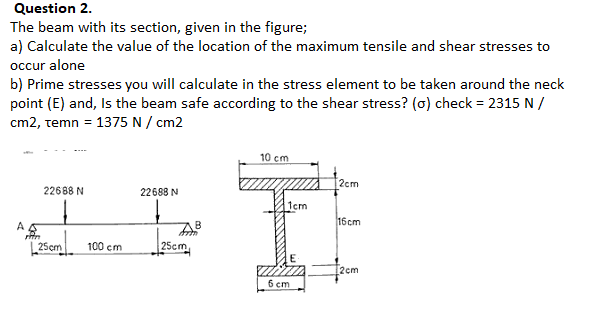
Transcribed Image Text:The beam with its section, given in the figure;
a) Calculate the value of the location of the maximum tensile and shear stresses to
occur alone
b) Prime stresses you will calculate in the stress element to be taken around the neck
point (E) and, Is the beam safe according to the shear stress? (0) check = 2315 N /
cm2, temn = 1375 N / cm2
%3D
Expert Solution
This question has been solved!
Explore an expertly crafted, step-by-step solution for a thorough understanding of key concepts.

Step by step
Solved in 4 steps with 4 images

Knowledge Booster


Learn more about
Need a deep-dive on the concept behind this application? Look no further. Learn more about this topic, mechanical-engineering and related others by exploring similar questions and additional content below.Recommended textbooks for you
Mechanics of Materials (MindTap Course List)
Mechanical Engineering
ISBN:
9781337093347
Author:
Barry J. Goodno, James M. Gere
Publisher:
Cengage Learning
Mechanics of Materials (MindTap Course List)
Mechanical Engineering
ISBN:
9781337093347
Author:
Barry J. Goodno, James M. Gere
Publisher:
Cengage Learning