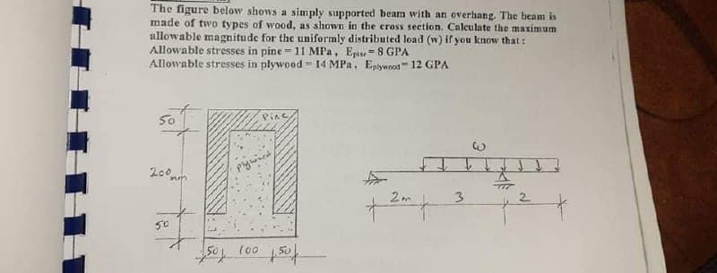
The figure below shows a simply supported beam with an overbang. The beam is made of two types of wood, as shown in the cross section. Calculate the maximum allowable magnitude for the uniformly distributed load (w) if you know that: Allowable stresses in pine =11 MPa, Epie =8 GPA Allowable stresses in plywood = 14 MPa. Epywood 12 GPA
Q: For the box beam shown in Fig. if the modulus of elasticity E = 200 GPa, the flexural stresses at…
A:
Q: Homework; In Figure below, a cantilever beam is subjected to an inclined force (P); calculate: 1-…
A:
Q: A bending moment of M=150 kips-in is applied at the cross section of beam shown in Figure Question…
A:
Q: 2. As shown in the figure, a rigid beam with negligible mass is pinned at one end and supported by…
A:
Q: 10 kN 3 kN/m 100 mm 200 mm B 1.5 m 1.5 m 2.2 m
A:
Q: 4.44 For the 8-in. I-beam shown in figure below, compute the maximum transverse shear stress (use…
A: First let us determine the moment of inertia of the section Moment of inertia about neutral axis =…
Q: A simply supported beam ABCD is subjected to a linearly distributed load, with wo = 100 N/m, two…
A:
Q: A steel cantilever beam with a 1-in-diameter round cross section and length of 10 in is loaded at…
A: Given data:
Q: |1200 Ib | 1200 Ib 3 ft R2
A: Note: As per bartelby guideline first three subpart are solved. please upload other part separately…
Q: A 5.15-N beam of uniform density is 1.70 m long. The beam is supported at an angle of 35.0° by a…
A:
Q: A simple beam of span length 3.2 m carries auniform load of intensity 48 kN/m. The cross sectionof…
A: Given data: The length of the simple beam is L = 3.2 m. The uniform load can be given as F = 48 kN/m…
Q: AB beam three rectangular planks obtained by gluing and as shown in the figure has been loaded.…
A: Free Body Diagram of the body Now we will calculate the support reactions,As we can see…
Q: situation; a) Maximum normal stress
A:
Q: (a) A steel cantilever beam with a 1-in-diameter round cross section and length of 10 in is loaded…
A: Stresses are developed in machine elements due to applied load. Machine design involves ensuring…
Q: Q2\ For the composite section beam shown in figure below. Determine the maximum bending stresses.…
A: ratio of elastic modulii = 200/25 = 8 we have to develop the equivalent section for solving the sum…
Q: For the box beam shown in Fig. if the modulus of elasticity E = 200 GPa, the %3D flexural stresses…
A:
Q: A simply supported beam -b<y<b, 0 <x<L, as shown below, is subjected to a compressive load of half…
A: σy= -3 4bx δ2Mδx2[y33b2-y] +c3f(x)+c4σy=0 at uy=-bc3f(x)+c4=34 δ2Mσx2 x 23= σy=-3…
Q: 10.4-13 Beam ABC is fixed at support A and rests (at point B) upon the midpoint of beam DE (see the…
A: The deflection diagram of the beam without considering beam DE is given as, The maximum deflection…
Q: The composite beam in the figure is made of steel and aluminum. Beam In steel and aluminum as it is…
A: Given: Esteel=210GPa Eal=70GPa M=2kNm Solution: The position of the neutral axix is exactly at the…
Q: The figure shows a cantilever consisting of steel angles size 100 x 100 x 12 mm mounted back to…
A: given data; ⇒w=1KN/mF=2.5KN⇒OA=2m⇒OB=3m⇒AB=1m
Q: The thin-walled single cell beam shown in Figure has been idealized into a combination of direct…
A:
Q: Consider a wood beam (see figure) carrying a uniform load of 13.5 kN/m (which includes the weight of…
A: In this part, each part is having 2 unknowns so we will solve first part for you. Please resubmit…
Q: The homogeneous beam shown in the figure is suspended by a cable at point B and is pin supported at…
A:
Q: EIn the Figure below, a cantilever beam is subjected to an inclined force (P); calculate the: 1-…
A: (a) The normal stress: 144.3375 kPa. (b) The shear stress: 83.3333 kPa.
Q: Ex: For a simple beam of length (L) subject to a concentrated load (P), shown in figure, Find : 1.…
A: Since, all the three parts are different question. And, as per the guidelines, I can solve only one…
Q: Q1: The horizontal rigid beam ABCD is supported by vertical bars BE and CF and is loaded by vertical…
A:
Q: Consider the beam shown in sketch below, hinge supported at point A and roller supported at point D.…
A: Considering the cross-section of the beam The web is denoted as 1 and flange is denoted as 2
Q: Figure Q1 shows one ‘L’ shaped beam ACD which is built-in at one end. It is loaded with load F=3 kN…
A:
Q: A simply supported wood beam is subjected to uniformly distributed load q. The width of the beam is…
A: We have to first find out the shear force and bending moment at point C. Then, the normal stresses…
Q: A simply supported composite beam 2 m long carries a uniformly distributed load of intensity q = 2.3…
A: (a) To Find : The maximum bending σw and σs. Given : The uniformly distributed load intensity is :…
Q: he composite beam shown in the Figure below is formed of a wood beam and a steel inforcing plate.…
A: M=60 kips.in. Ew=1500 ksiEs=30000 ksi Let wood of reference material, For wood n=1 For steel…
Q: Ahorizontal beam AB with cross-sectional dimensions 4 ft -5 ft Ab # 075 in.)X h#8.0 in. is supported…
A:
Q: Figure Q2 shows the cross section of a beam. The beam is simply supported over a span of 6 m and…
A:
Q: In the beam loading system given below, A is a simple and C is a sliding support. The outer diameter…
A:
Q: 1. Find the maximum tensile and compressive flexural stresses for the cantilever beam with loading…
A:
Q: The composite beam shown in the Figure below is formed of a wood beam and a steel reinforcing plate.…
A:
Q: A timber beam is subjected to loads as shown in the following figure If the allowable tensile and…
A: Beam is subjected to both shear stress and bending moment. To consider the maximum safety dimension…
Q: 35 KN 15 KN 30 KN 10 KN O18 m 1:0 m 0,6 m
A:
Q: A small steel T beam is usedin an inverted position to span 400 [mm]. If, due to the application of…
A:
Q: HOMEWORK: Q1/ A beam carries the loads shown in figure, if the tensile stress must not exceed 20 MPa…
A: Find load P
Q: (a) A steel cantilever beam with a 1-in-diameter round cross section and length of 10 in is loaded…
A: Given dataDiameter of the round cross section d= 1inchLength of the bar L = 10inApplied transverse…
Q: A 3m x 3m x 76 mm thick precast slab is lifted by a crane by using cables on lift-up points provided…
A:
Q: For the box beam shown in Fig. if the modulus of elasticity E 200 GPa, the flexural stresses at…
A:
Q: 3.03 The beam shown below is an aluminum channel, C 100 x 50 x 25.79, positioned with the legs down…
A: Given: The channel width, b = 100 mm The channel height, h = 50 mm The web thickness, t = 25.79 mm
Q: In the Figure below, a cantilever beam is subjected to an inclined force (P); calculate the: 1-…
A:
Q: The hollow circle cross section of the simply supported beam shown in the figure. Find the maximum…
A: For solution refer below images.
Q: A flat bar of rectangular cross section, length L, and constant thickness tis subjected to tension…
A:
Q: 40 men D Steel t-200 GPa The rigid beam (ABC) supported by three bars, One from the top and two from…
A:
Q: Determine the maximum tensile stress er and maximum compressive stress ec due to the load P acting…
A:
Q: * The hollow circle cross section of the simply supported beam shown in the figure. Find the maximum…
A: For solution refer below images.
Trending now
This is a popular solution!
Step by step
Solved in 4 steps with 6 images
- A retaining wall 6 ft high is constructed of horizontal wood planks 2.5 in. thick (actual dimension) that are supported by vertical wood piles of a 12 in, diameter (actual dimension), as shown in the figure. The lateral earth pressure is pt=125 lb/ft2 at the top of the wall and p2= 425 lb/ft2 at the bottom. Assuming that the allowable stress in the wood is 1175 psi, calculate the maximum permissible spacing s of the piles. Find the required diameter of the wood piles so that piles and planks (f = 2.5 in.) reach the allowable stress at the same time. Hint: Observe that the spacing of the piles may be governed by the load-carrying capacity of either the planks or the piles. Consider the piles to act as cantilever beams subjected to a trapezoidal distribution of load, and consider the planks to act as simple beams between the piles. To be on the safe side, assume that the pressure on the bottom plank is uniform and equal to the maximum pressure.A bimetallic beam used in a temperature-control switch consists of strips of aluminum and copper bonded together as shown in the figure, which is a cross-sectional view. The width of the beam is LO in,, and each strip has a thickness of 1/16 in. Under the action of a bending moment M = 12 lb-in, acting about the z axis, what are the maximum stresses aaand ecin the aluminum and copper, respectively? (Assume fA, = 10,5 x l0 psi and ecu= 16,8 × 10⁶ psi,)A plastic bar of rectangular cross section (ft = 1.5 in. and h = 3 in.) fits snugly between rigid supporls at room temperature (68oF) but with no initial stress (see Figure). When the temperature of the bar is raised to 160oF, the compressive stress on an inclined plane pq at mid-span becomes 1700 psi. (a) What is the shear stress on plane pq? (Assume a = 60 × 10-6/*t and E = 450 × 103psi.) (b) Draw a stress element oriented to plane pq and show the stresses acting on all laces of this element. (c) If the allowable normal stress is 3400 psi and the allowable shear stress is 1650 psi. what is the maximum load P (in the positive x direction), which can be added at the quarter point (in addition to thermal effects given) without exceeding allowable stress values in the bar?
- A standard brick (dimensions 8 in. × 4 in. × 2.5 in ) is compressed lengthwise by a force P. as shown in the figure, If the ultimate shear stress for brick is 1200 psi and the ultimate compressive stress is 3600 psi. what force Pmax is required to break the brick?A thin-walled circular tube and a solid circular bar of the same material (see figure) are subjected to torsion. The tube and bar have the same cross-sectional area and the same length. What is the ratio of the strain energy U1in the tube to the strain energy U2in the solid bar if the maximum shear stresses are the same in both cases? (For the tube, use the approximate theory for thin-walled bars.)A simple beam of span length 3.2 m carries a uniform load of intensity 48 kN/m, The cross section of the beam is a hollow box with wood flanges and steel side plates, as shown in the figure. The wood flanges are 75 mm x 100 mm in cross section, and the steel plates are 300 mm deep. What is the required thickness t of the steel plates if the allowable stresses are 120 M Pa for the steel and 6,5 M Pa for the wood? (Assume that the moduli of elasticity for the steel and wood are 210 GPa and 10 GPa, respectively, and disregard the weight of the beam.)
- A cantilever beam(Z, = 6 ft) with a rectangular cross section (/> = 3.5 in., h = 12 in.) supports an upward load P = 35 kips at its free end. (a) Find the state of stress ((7T, o^., and r in ksi) on a plane-stress element at L/2 that is i/ = 8 in. up from the bottom of the beam. Find the principal normal stresses and maximum shear stress. Show these stresses on sketches of properly oriented elements. (b) Repeat part (a) if an axial compressive centroidal load N = 40 kips is added at BTruss members supporting a roof are connected to a 26-mm-thick gusset plate by a 22-mm diameter pin, as shown in the figure and photo. The two end plates on the truss members are each 14 mm thick. (a) If the load P = 80 kN, what is the largest bearing stress acting on the pin? (b) If the ultimate shear stress for the pin is 190 MPa, what force Pult is required to cause the pin to fail in shear? Disregard friction between the plates.A reinforced concrete slab (see figure) is reinforced with 13-mm bars spaced 160 mm apart at d = 105 mm from the top of the slab. The modulus of elasticity for the concrete is Ec= 25 GPa, while that of the steel is £s = 200 G Pa. Assume that allowable stresses for concrete and steel arecrac = 9.2 MPa and us = 135 MPa. l()5 mm Find the maximum permissible positive bending moment for a l-m wide strip of the slab. What is the required area of steel reinforcement, A^ if a balanced condition must be achieved? What is the allowable positive bending moment? (Recall that in a balanced design, both steel and concrete reach allowable stress values simultaneously under the design moment.)
- A vertical pole of solid, circular cross section is twisted by horizontal forces P = 5kN acting at the ends of a rigid horizontal arm AB (see figure part a). The distance from the outside of the pole to the line of action of each force is c = 125 mm (sec figure part b) and the pole height L = 350 mm. (a) If the allowable shear stress in the pole is 30 MPa, what is the minimum required diameter dminof the pole? (b) What is the torsional stiffness of the pole (kN · m/rad)? Assume that G = 28 GPa. (c) If two translation al springs, each with stiffness k =2550 kN/m, are added at 2c/5 from A and B (see figure part c), repeat part (a) to find dmin. Hint: Consider the pole and pair of springs as "springs in parallel."Segments A B and BCD of beam A BCD are pin connected at x = 4 m. The beam is supported by a sliding support at A and roller supports at C and D (see figure). A triangularly distributed load with peak intensity of SO N/m acts on EC. A concentrated moment is applied at joint D. (a) Find reactions at supports A, C, and D. (b) Find internal stress resultants N, Y, and Mat x = 5m. (c) Repeat parts (a) and (b) for die case of the roller support at C replaced by a linear spring of stiffness kr™ 200 kN/m (see figure).A large precast concrete panel for a warehouse is raised using two sets of cables at two lift lines, as shown in the figure part a. Cable 1 has a length L1 = 22 Ft, cable 2 has a length L2= 10 ft, and the distance along the panel between lift points Band D is d = 14 ft (see figure part b). The total weight of the panel is W = 85 kips. Assuming the cable lift Forces F at each lift line are about equal, use the simplified model of one half of the panel in figure part b to perform your analysis for the lift position shown. Find the required cross-sectional area AC of the cable if its breaking stress is 91 ksi and a factor of safety of 4 with respect to failure is desired.