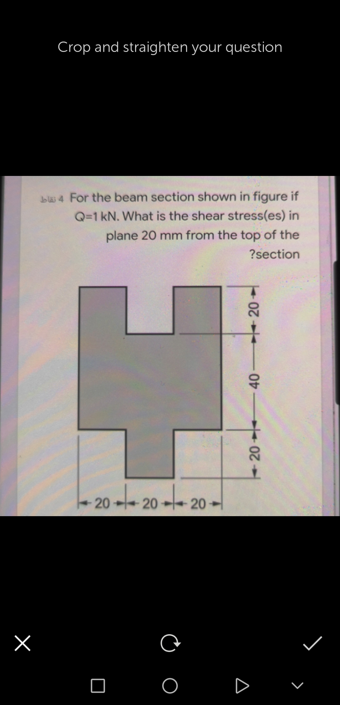
blas 4 For the beam section shown in figure if Q=1 kN. What is the shear stress(es) in plane 20 mm from the top of the ?section


Q: Q 1: A simply supported beam as shown in figure (1-A) below, having an I-cross section, has an over…
A:
Q: OD aluminum steel A composite beam is a built-up section made of aluminium and reinforced with a…
A:
Q: fF=6 kN as in the figure. Find the maximum normal stress occurring in section (a-b). Sh ne stress…
A: Answer is given below
Q: A bending moment of M=150 kips-in is applied at the cross section of beam shown in Figure Question…
A:
Q: Question 6 For the loaded beam shown in Figure Q6 below, consider section M-M and determine the…
A:
Q: 10 kN 3 kN/m 100 mm 200 mm B 1.5 m 1.5 m 2.2 m
A:
Q: The vertical shear force acting in a beam with the cross section shown in the figure is 20 kips.…
A:
Q: Calculate the shear stress of the beam in the figure at point “a”?
A: Moment of inertia of an area is defined as the product of area and the distances of its center from…
Q: |1200 Ib | 1200 Ib 3 ft R2
A: Note: As per bartelby guideline first three subpart are solved. please upload other part separately…
Q: The cross-sectional dimensions of the beam shown in Figure are ro = 115 mm and ri = 95 mm. Given Mz…
A: Moment of inertia is given asI=π64D4-d4I=π642×1154-2×954I=73.39×106 mm4perpenficular distance…
Q: 25 kips 20 in.- Figure 1 10 in. 25 kips 20 in. B 7.25 in. Sin.- b 1.5 in. 1.5 in.
A:
Q: A beam is loaded as shown in the below figure. Then the bending stress along the x-x line is 5 kN 2…
A: The formula for the bending stress is. MI=σyσ=MyI Here, M is bending moment, I is moment of inertia…
Q: situation; a) Maximum normal stress
A:
Q: A simple beam is loaded as shown in the figure below If the load P 120 kN determine the maximum…
A: Normal stress will be maximum at cross section 'B'Net normal stress = Normal stressaxial+Normal…
Q: By drawing N-V-M-Ɵ-y diagrams in the loading case in the figure below,Since the AB steel circular…
A:
Q: A cantilever beam with length, L = 5 m, is supporting a downward concentrated load, P = 88 kN, at…
A:
Q: The composite beam in the figure is made of steel and aluminum. Beam In steel and aluminum as it is…
A: Given: Esteel=210GPa Eal=70GPa M=2kNm Solution: The position of the neutral axix is exactly at the…
Q: The beam shown in the figure is made of Wood that has an Allowable Shear Stress of 200 psi;…
A:
Q: The thin-walled single cell beam shown in Figure has been idealized into a combination of direct…
A:
Q: Consider a wood beam (see figure) carrying a uniform load of 13.5 kN/m (which includes the weight of…
A: In this part, each part is having 2 unknowns so we will solve first part for you. Please resubmit…
Q: Problem 1) Cross section of a beam was shown in the below figure. Suppose that this beam is…
A: Given: The bending moment, M = 10 kN.m
Q: Determine the flexural stress and shear stress of a rectangular beam loaded as shown in the figure…
A: Given data: For hallow rectangle the loading diagram is given below
Q: A simply supported beam (i.e., with a pin support at point A and a roller support at point D) is…
A:
Q: Find the absolute maximum bending stress in the beam shown in the figure below. (Figure 3) The beam…
A:
Q: The cross-sectional beam shown in the figure is subject to a maximum shear stress of 35 ksi, due to…
A:
Q: Calculate the maximum shear stress τmax and the maximum bending stress σmax in a wood beam (see…
A: Draw the free body diagram of simple supported beam-
Q: In the simple beam given in the figure, Find the maximum slope and depression using the values.…
A: When any beam is subjected to a load, it deflects, and the neutral axis becomes a curved line which…
Q: The beam with its section, given in the figure; a) Calculate the value of the location of the…
A:
Q: The overhanging beam shown in Figure 2 is subjected to two point loads, P at the free end D and 2P…
A:
Q: if the cross-section shown in the figure has shear stress of 300psi at point P( located 0.25 in…
A:
Q: The beam in the figure below is made from three boards nailed together as shown, If the internal…
A:
Q: In the beam loading system given below, A is a simple and C is a sliding support. The outer diameter…
A:
Q: The composite beam shown in the Figure below is formed of a wood beam and a steel reinforcing plate.…
A:
Q: As a result of the loading condition given in the I-section fixed beam shown in the figure;…
A: When a cantilever is applied a point load at the free end it tends to get bend. It will experience…
Q: Rectangular cross-section and width given the loading state in the figure Bending safety stress of…
A:
Q: HOMEWORK: Q1/ A beam carries the loads shown in figure, if the tensile stress must not exceed 20 MPa…
A: Find load P
Q: Draw diagram shear force and bending moment to cantilever beam which shown in the figure. W=5 KN/m…
A: The Shear Force Diagram (SFD) and Bending Moment Diagram (BMD) are very important tools to analyze a…
Q: A simply supported beam (i.e., with a pin support at point A and a roller support at point D) is…
A:
Q: Calculate the maximum shear stress o h, 10.1 in., and the shear force V = 4,700 Ib. (Enter the…
A: Givenb=14int=0.5inh=11inh1=10.1inV=4700lb
Q: A beam having a cross section in the formof a channel (see figure) is subjected to a bendingmoment…
A: Given Beam ratio = 7:3 To find Magnitude of t
Q: 2. The cantilever beam shown in the figure below is subjected to loads P, = 3 kips and P, = 8.5…
A:
Q: In the Figure below, a cantilever beam is subjected to an inclined force (P); calculate the: 1-…
A:
Q: Q: For the cantilever beam with uniformly distributed load shown in Figure find; a The maximum shear…
A: As per company policy, we are restricted to solve only the first three sub-part of one question at a…
Q: b) The simply supported beam as shown in Figure 2 is made of five planks glued together at A and B.…
A:
Q: aluminum steel A composite beam is a built-up section made of aluminium and reinforced with a steel…
A:
Q: * The hollow circle cross section of the simply supported beam shown in the figure. Find the maximum…
A: For solution refer below images.
Q: The cross-sectional dimensions of the beam shown in Figure are ro = 115 mm and ri = 95 mm. Given Mz…
A:

Step by step
Solved in 4 steps with 10 images


- A cantilever beam of length L = 2 m supports a load P = 8,0 kN (sec figure). The beam is made of wood with cross-sectional dimensions 120 mm x 200 mm. Calculate the shear stresses due to the load/"at points located 25 mm, 50 mm, 75 mm, and 100 mm from the top surface of the beam. From these results, plot a graph showing the distribution of shear stresses from top to bottom of the beam.A steel beam of length L = 16 in. and cross-sectional dimensions h = 0.6 in. and h = 2 in. (see figure) supports a uniform load of intensity if = 240 lb/in., which includes the weight of the beam. Calculate the shear stresses in the beam (at the cross section of maximum shear force) at points located 1/4 in., 1/2 in., 3/4 in., and I in, from the top surface of the beam. From these calculations, plot a graph showing the distribution of shear stresses from top to bottom of the beam.A cantilever beam(Z, = 6 ft) with a rectangular cross section (/> = 3.5 in., h = 12 in.) supports an upward load P = 35 kips at its free end. (a) Find the state of stress ((7T, o^., and r in ksi) on a plane-stress element at L/2 that is i/ = 8 in. up from the bottom of the beam. Find the principal normal stresses and maximum shear stress. Show these stresses on sketches of properly oriented elements. (b) Repeat part (a) if an axial compressive centroidal load N = 40 kips is added at B
- Calculate the distance e from the centerline of the web of a C 310 × 45 channel section to the shear center E (see figure). Note: For put poses of analysis, consider the flanges to be rectangles with thickness îrequal to the average flange thickness given in Table F-3(b) in Appendix F.During construction of a highway bridge, the main girders are cantilevered outward from one pier toward the next (see figure). Each girder has a cantilever length of 48 m and an I-shaped cross section with dimensions shown in the figure. The load on each girder (during construction) is assumed to be 9,5 kN/m, which includes the weight of the girder. Determine the maximum bending stress in a girder due to this load.A beam of wide-flange shape, W 8 x 28, has the cross section shown in the figure. The dimensions are b = 6.54 in., h = 8.06 in., fw = 0.285 in., and tf = 0.465 in.. The loads on the beam produce a shear force V = 7.5 kips at the cross section under consideration. Use center line dimensions to calculate the maximum shear stress raiaxin the web of the beam. Use the more exact analysis of Section 5,10 in Chapter 5 to calculate the maximum shear stress in the web of the beam and compare it with the stress obtained in part .
- Calculate the distance e from the cent crime of the web of a C 15 x 40 channel section to the shear center 5 (see figure). Note: For purposes of analysis, consider the flanges to be rectangles with thickness teequal to the average flange thickness given in Table F-3(a) in Appendix F.Two wood beams, each of rectangular cross section (3.0 in. x 4.0 in., actual dimensions), are glued together to form a solid beam with dimensions 6.0 in. x 4.0 in. (sec figure). The beam is simply supported with a span of S ft. What is the maximum moment Mmaxthat may be applied at the left support if the allowable shear stress in the glued joint is 200 psi? (Include the effects of the beams own weight, assuming that the wood weighs 35 lb/ft3.) Repeat part (a) if Mmaxis based on allowable bending stress of 2500 psi.Each girder of the lift bridge (sec figure) is 180 ft long and simply supported at the ends. The design load for each girder is a uniform load of intensity 1,6 kips/ft. The girders are fabricated by welding three steel plates to form an I-shaped cross section (see figure) having section modulus S = 3600 in3. What is the maximum bending stress rmaxin a girder due to the uniform load?
- A steel plate (called a cover ploie) having cross-sectional dimensions 6,0 in. × 0.5 in. is welded along the full length of the bottom flange of a W 12 × 50 wide-flange beam (sec figure, which shows the beam cross section). What is the percent increase in the smaller section modulus (as compared to the wide-flange beam alone)?. A cantilever beam (width b = 3 in. and depth h = 6 in,) has a length L = 5 ft and is subjected to a point load P and a concentrated moment M = 20 kip-ft at end B. If normal stress trx= 0 at point C, located 0.5 in. below the top of the beam and 1 ft to the right of point Atfind point load P. Also show the complete state of plane stress on the element at point C.A bimetallic beam used in a temperature-control switch consists of strips of aluminum and copper bonded together as shown in the figure, which is a cross-sectional view. The width of the beam is LO in,, and each strip has a thickness of 1/16 in. Under the action of a bending moment M = 12 lb-in, acting about the z axis, what are the maximum stresses aaand ecin the aluminum and copper, respectively? (Assume fA, = 10,5 x l0 psi and ecu= 16,8 × 10⁶ psi,)