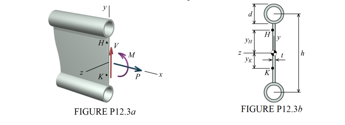
The doubly-symmetric beam cross section shown in Figure P12.3b has been proposed for a short foot bridge. The cross section will consist of two identical steel pipes that are securely welded to a steel web plate that has a thickness of t = 9.5 mm. Each pipe has an outside diameter of d = 70 mm and a wall thickness is 5 mm. The distance between the centers of the two pipes is h = 370 mm. Internal forces of P = 13 kN, V = 25 kN, and M = 9 kN·m act in the directions shown in Figure P12.3a. Determine the stresses acting on horizontal and vertical planes: (a) at point H, which is located at a distance of yH = 120 mm above the z centroidal axis. (b) at point K, which is located at a distance of yK = 80 mm below the z centroidal axis. Show the stresses on a stress element for each point


The doubly-symmetric beam cross section shown in Figure P12.3b has been proposed for
a short foot bridge. The cross section will consist of two identical steel pipes that are securely
welded to a steel web plate that has a thickness of t = 9.5 mm. Each pipe has an outside diameter
of d = 70 mm and a wall thickness is 5 mm. The distance between the centers of the two pipes is
h = 370 mm. Internal forces of P = 13 kN, V = 25 kN, and M = 9 kN·m act in the directions
shown in Figure P12.3a. Determine the stresses acting on horizontal and vertical planes:
(a) at point H, which is located at a distance of yH = 120 mm above the z centroidal axis.
(b) at point K, which is located at a distance of yK = 80 mm below the z centroidal axis.
Show the stresses on a stress element for each point.


Trending now
This is a popular solution!

Step by step
Solved in 3 steps with 3 images


