The effective impedances of the main and auxiliary windings of a capacitor-start induction motor under locked-rotor conditions are given as follows: Main winding: effective resistance = 5.3 Q; effective reactance = 9.6 Q Auxiliary winding: effective resistance = 7.5 Q; effective reactance = 3.2 N If the VL is 150 V, a. Illustrate the equivalent circuit and determine the magnitude of real, reactive and apparent powers from the main and auxiliary windings. b. Calculate the phase angle between la and Is. c. Calculate the line current IL. d. Determine the power factor under locked-rotor conditions.
The effective impedances of the main and auxiliary windings of a capacitor-start induction motor under locked-rotor conditions are given as follows: Main winding: effective resistance = 5.3 Q; effective reactance = 9.6 Q Auxiliary winding: effective resistance = 7.5 Q; effective reactance = 3.2 N If the VL is 150 V, a. Illustrate the equivalent circuit and determine the magnitude of real, reactive and apparent powers from the main and auxiliary windings. b. Calculate the phase angle between la and Is. c. Calculate the line current IL. d. Determine the power factor under locked-rotor conditions.

Power System Analysis and Design (MindTap Course List)
6th Edition
ISBN:9781305632134
Author:J. Duncan Glover, Thomas Overbye, Mulukutla S. Sarma
Publisher:J. Duncan Glover, Thomas Overbye, Mulukutla S. Sarma
Chapter2: Fundamentals
Section: Chapter Questions
Problem 2.21P: An industrial plant consisting primarily of induction motor loads absorbs 500 kW at 0.6 power factor...

Related questions

Question
w8
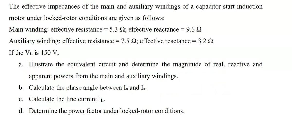
Transcribed Image Text:The effective impedances of the main and auxiliary windings of a capacitor-start induction
motor under locked-rotor conditions are given as follows:
Main winding: effective resistance = 5.3 2; effective reactance = 9.6 2
Auxiliary winding: effective resistance = 7.5 2; effective reactance = 3.2 2
If the VL is 150 V,
a. Illustrate the equivalent circuit and determine the magnitude of real, reactive and
apparent powers from the main and auxiliary windings.
b. Calculate the phase angle between Ia and Is.
c. Calculate the line current IL.
d. Determine the power factor under locked-rotor conditions.
Expert Solution
This question has been solved!
Explore an expertly crafted, step-by-step solution for a thorough understanding of key concepts.

Step by step
Solved in 2 steps with 1 images

Knowledge Booster


Learn more about
Need a deep-dive on the concept behind this application? Look no further. Learn more about this topic, electrical-engineering and related others by exploring similar questions and additional content below.Recommended textbooks for you
Power System Analysis and Design (MindTap Course …
Electrical Engineering
ISBN:
9781305632134
Author:
J. Duncan Glover, Thomas Overbye, Mulukutla S. Sarma
Publisher:
Cengage Learning
Power System Analysis and Design (MindTap Course …
Electrical Engineering
ISBN:
9781305632134
Author:
J. Duncan Glover, Thomas Overbye, Mulukutla S. Sarma
Publisher:
Cengage Learning