Análisis de rectificador onda completa Consider the capacitor-filter rectifier circuit as shown in Figure 1. The input is a single-phase source that is derived from a 220 Vrms mains. Tasks for analysis: (a) Rig up the circuit as shown in Figure land plot V and i versus time. (b) Why is there ringing on the current wave-form? (c) What is the series impedance of the circuit? (d) Plot V, and V. versus time, What is the ripple? How does ripple depend on load, capacitor C, and frequency of input wave-form? (e) Measure the current and voltage waveform across the rectifier diode. (f) Estimate the average and ms currents through the rectifier diode, Calculate the diode power dissipation. (g) What should be the peak current rating of the diode? (h) Change the initial charge voltage on the capacitor Cr. What is the effect on the input surge current? (i) Change the phase angle of the input V, at start up. Observe the effect on current i. What happens and why? 0) Under what conditions do you get maximum peak current to flow through the diodes (k) Measure the input voltage and current and estimate the power factor. (1) What is the effect of change in C, value on the input current and power factor? (m) Choose a suitable value for R and construct a simulation model in LTspice and verify your analytic results.
Análisis de rectificador onda completa Consider the capacitor-filter rectifier circuit as shown in Figure 1. The input is a single-phase source that is derived from a 220 Vrms mains. Tasks for analysis: (a) Rig up the circuit as shown in Figure land plot V and i versus time. (b) Why is there ringing on the current wave-form? (c) What is the series impedance of the circuit? (d) Plot V, and V. versus time, What is the ripple? How does ripple depend on load, capacitor C, and frequency of input wave-form? (e) Measure the current and voltage waveform across the rectifier diode. (f) Estimate the average and ms currents through the rectifier diode, Calculate the diode power dissipation. (g) What should be the peak current rating of the diode? (h) Change the initial charge voltage on the capacitor Cr. What is the effect on the input surge current? (i) Change the phase angle of the input V, at start up. Observe the effect on current i. What happens and why? 0) Under what conditions do you get maximum peak current to flow through the diodes (k) Measure the input voltage and current and estimate the power factor. (1) What is the effect of change in C, value on the input current and power factor? (m) Choose a suitable value for R and construct a simulation model in LTspice and verify your analytic results.

Power System Analysis and Design (MindTap Course List)
6th Edition
ISBN:9781305632134
Author:J. Duncan Glover, Thomas Overbye, Mulukutla S. Sarma
Publisher:J. Duncan Glover, Thomas Overbye, Mulukutla S. Sarma
Chapter12: Power System Controls
Section: Chapter Questions
Problem 12.2P

Related questions
Question
Transcribed Image Text:9.
9.
R
V.
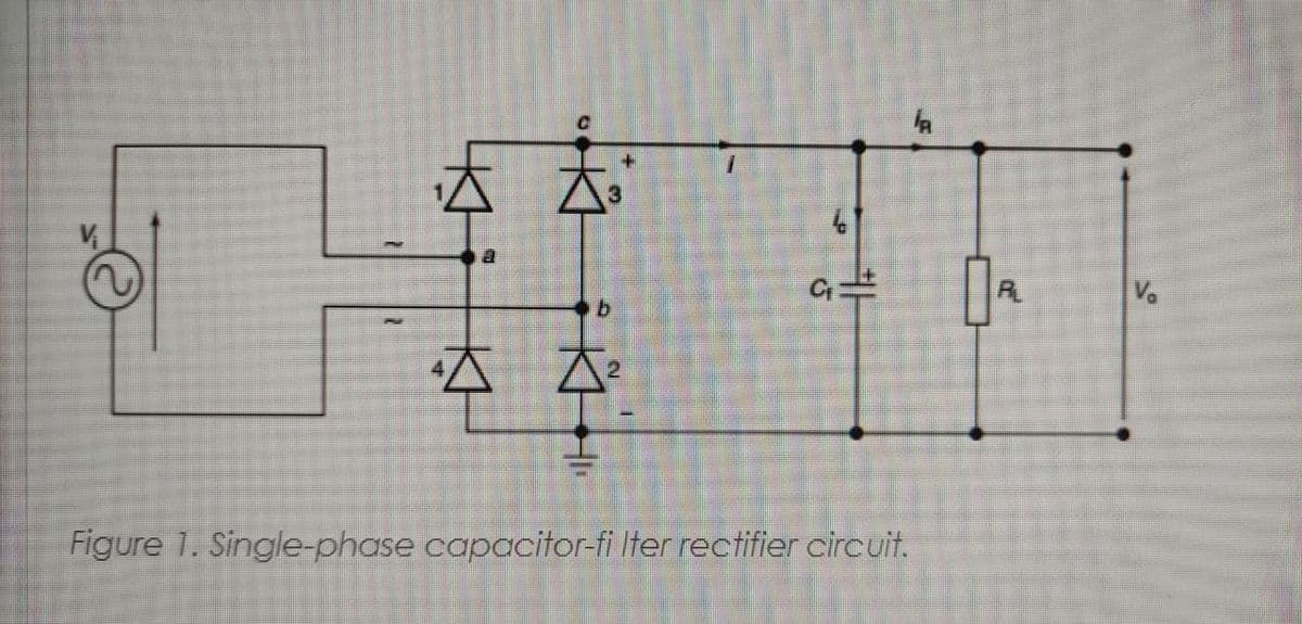
Figure 1. Single-phase capacitor-fi Iter rectifier circuit.
Transcribed Image Text:Análisis de rectificador onda completa
Consider the capacitor-filter rectifier circuit as shown in Figure 1. The input is a single-phase source that is derived from a 220 Vrms mains. Tasks for analysis:
(a) Rig up the circuit as shown in Figure land plot V andi versus time.
(b) Why is there ringing on the current wave-form?
(c) What is the series impedance of the circuitệ
(d) Plot V and V. versus time. What is the ripple? How does ripple depend on load, capacitor C; and frequency of input wave-form?
(e) Measure the current and voltage waveform across the rectifier diode.
(f) Estimate the average and ms currents through the rectifier diode, Calculate the diode power dissipation.
(g) What should be the peak current rating of the diode?
(h) Change the initial charge voltage on the capacitor Cr. What is the effect on the input surge current?
(i) Change the phase angle of the input V, at start up. Observe the effect on current i. What happens and why?
1) Under whaf conditions do you get maimum peak current to flow through the diodes?
(k) Measure the input voltage and current and estimate the power factor.
(1) What is the effect of change in Cr value on the input current and power factor?
(m) Choose a suitable value for R and construct a simulation model in LTspice and verify your analytic results.
Expert Solution
This question has been solved!
Explore an expertly crafted, step-by-step solution for a thorough understanding of key concepts.

Step by step
Solved in 2 steps with 2 images

Knowledge Booster


Learn more about
Need a deep-dive on the concept behind this application? Look no further. Learn more about this topic, electrical-engineering and related others by exploring similar questions and additional content below.Recommended textbooks for you
Power System Analysis and Design (MindTap Course …
Electrical Engineering
ISBN:
9781305632134
Author:
J. Duncan Glover, Thomas Overbye, Mulukutla S. Sarma
Publisher:
Cengage Learning

Delmar's Standard Textbook Of Electricity
Electrical Engineering
ISBN:
9781337900348
Author:
Stephen L. Herman
Publisher:
Cengage Learning
Power System Analysis and Design (MindTap Course …
Electrical Engineering
ISBN:
9781305632134
Author:
J. Duncan Glover, Thomas Overbye, Mulukutla S. Sarma
Publisher:
Cengage Learning
Delmar's Standard Textbook Of Electricity
Electrical Engineering
ISBN:
9781337900348
Author:
Stephen L. Herman
Publisher:
Cengage Learning