The one-line diagram of an unloaded power system is shown below. T | 1000 T Reactances of the two sections of transmission line are shown in the diagram. The generators and transformers are rated as follows: Generator 1: 20 MVA 13.8 KV, X = 0.2 per unit Generator 2: 30 MVA, 18 KV, X= 0.2 per unit Generator 3: 30 MVA, 20 KV, X = 0.2 per unit Transformer T1: 25 MVA, 220Y/13.8A KV, X= 10% Transformer T: Single-phase units each rated 10 MVA, 127/18 KV, X = 10% Transformer T: 35 MVA, 220Y/22Y kV, X = 10% Compute for the reactances per unit and by choosing a base of 50 MVA 13.8KV in the circuit of generator 1. Show your complete solutions (41-48): 41. What is the generator 1 per unit reactance? a. 0.3333 b. 0.2755 c. 0.5 d. 0.2 42. What is the transformer 1 per unit reactance? a. 0.2 b. 0.1667 c. 0.1429 d. 0.0826 43. What is the transmission line 1 (point B to C) per unit reactance? a. 0.1033 b. 0.0826 C. 0.5 d. 0.2 44. What is the transformer 3 per unit reactance? a. 0.2 b. 0.1667 c. 0.1429 d. 0.0826 45. What is the transmission line 2 (point C to E) per unit reactance? a. 0.1033 c. 0.5 b. 0.0826 d. 0.2 46. What is the per unit reactance of the generator 3? a. 0.3333 b. 0.2755 c. 0.5 d. 0.2 47. What is the transformer 2 per unit reactance? a. 0.2 b. 0.1667 c. 0.1429 d. 0.0826 48 What is the generator 2 per unit reactance? a. 0.3333 b.0.2755 c. 0.5 d. 0.2
The one-line diagram of an unloaded power system is shown below. T | 1000 T Reactances of the two sections of transmission line are shown in the diagram. The generators and transformers are rated as follows: Generator 1: 20 MVA 13.8 KV, X = 0.2 per unit Generator 2: 30 MVA, 18 KV, X= 0.2 per unit Generator 3: 30 MVA, 20 KV, X = 0.2 per unit Transformer T1: 25 MVA, 220Y/13.8A KV, X= 10% Transformer T: Single-phase units each rated 10 MVA, 127/18 KV, X = 10% Transformer T: 35 MVA, 220Y/22Y kV, X = 10% Compute for the reactances per unit and by choosing a base of 50 MVA 13.8KV in the circuit of generator 1. Show your complete solutions (41-48): 41. What is the generator 1 per unit reactance? a. 0.3333 b. 0.2755 c. 0.5 d. 0.2 42. What is the transformer 1 per unit reactance? a. 0.2 b. 0.1667 c. 0.1429 d. 0.0826 43. What is the transmission line 1 (point B to C) per unit reactance? a. 0.1033 b. 0.0826 C. 0.5 d. 0.2 44. What is the transformer 3 per unit reactance? a. 0.2 b. 0.1667 c. 0.1429 d. 0.0826 45. What is the transmission line 2 (point C to E) per unit reactance? a. 0.1033 c. 0.5 b. 0.0826 d. 0.2 46. What is the per unit reactance of the generator 3? a. 0.3333 b. 0.2755 c. 0.5 d. 0.2 47. What is the transformer 2 per unit reactance? a. 0.2 b. 0.1667 c. 0.1429 d. 0.0826 48 What is the generator 2 per unit reactance? a. 0.3333 b.0.2755 c. 0.5 d. 0.2

Power System Analysis and Design (MindTap Course List)
6th Edition
ISBN:9781305632134
Author:J. Duncan Glover, Thomas Overbye, Mulukutla S. Sarma
Publisher:J. Duncan Glover, Thomas Overbye, Mulukutla S. Sarma
Chapter9: Unsymmetrical Faults
Section: Chapter Questions
Problem 9.5P

Related questions

Question
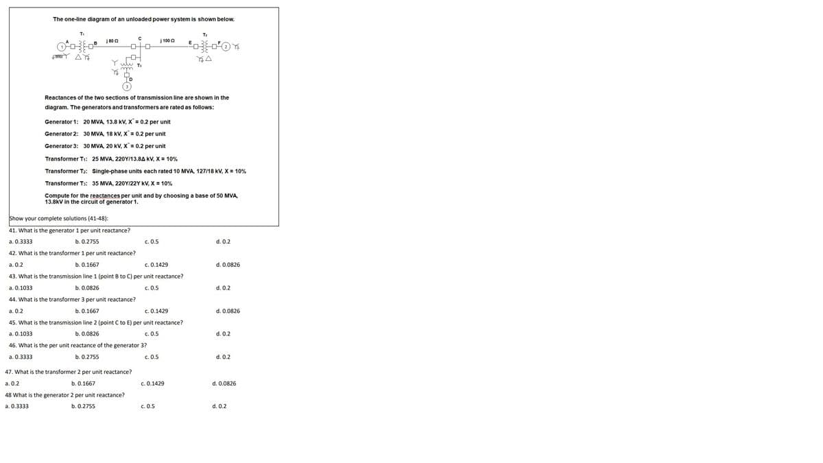
Transcribed Image Text:The one-line diagram of an unloaded power system is shown below.
T2
j 80 0
j 100 2
E
Y uw Ts
Reactances of the two sections of transmission line are shown in the
diagram. The generators and transformers are rated as follows:
Generator 1: 20 MVA, 13.8 kV, X" = 0.2 per unit
Generator 2: 30 MVA, 18 kV, X = 0.2 per unit
Generator 3: 30 MVA, 20 kV, X" = 0.2 per unit
Transformer T1: 25 MVA, 220Y/13.8A kV, X = 10%
Transformer T2: Single-phase units each rated 10 MVA, 127/18 kV, X = 10%
Transformer T3: 35 MVA, 220Y/22Y kV, X = 10%
Compute for the reactances per unit and by choosing a base of 50 MVA,
13.8kV in the circuit of generator 1.
Show your complete solutions (41-48):
41. What is the generator 1 per unit reactance?
a. 0.3333
b. 0.2755
c. 0.5
d. 0.2
42. What is the transformer 1 per unit reactance?
a. 0.2
b. 0.1667
c. 0.1429
d. 0.0826
43. What is the transmission line 1 (point B to C) per unit reactance?
a. 0.1033
b. 0.0826
c. 0.5
d. 0.2
44. What is the transformer 3 per unit reactance?
a. 0.2
b. 0.1667
c. 0.1429
d. 0.0826
45. What is the transmission line 2 (point C to E) per unit reactance?
a. 0.1033
b. 0.0826
c. 0.5
d. 0.2
46. What is the per unit reactance of the generator 3?
a. 0.3333
b. 0.2755
c. 0.5
d. 0.2
47. What is the transformer 2 per unit reactance?
а. О.2
b. 0.1667
c. 0.1429
d. 0.0826
48 What is the generator 2 per unit reactance?
a. 0.3333
b. 0.2755
c. 0.5
d. 0.2
Expert Solution
This question has been solved!
Explore an expertly crafted, step-by-step solution for a thorough understanding of key concepts.

This is a popular solution!

Trending now
This is a popular solution!

Step by step
Solved in 4 steps with 4 images

Knowledge Booster


Learn more about
Need a deep-dive on the concept behind this application? Look no further. Learn more about this topic, electrical-engineering and related others by exploring similar questions and additional content below.Recommended textbooks for you
Power System Analysis and Design (MindTap Course …
Electrical Engineering
ISBN:
9781305632134
Author:
J. Duncan Glover, Thomas Overbye, Mulukutla S. Sarma
Publisher:
Cengage Learning
Power System Analysis and Design (MindTap Course …
Electrical Engineering
ISBN:
9781305632134
Author:
J. Duncan Glover, Thomas Overbye, Mulukutla S. Sarma
Publisher:
Cengage Learning