The opposite beam is loaded with P=262.8 N and a distributed load w=65.7 N/m, The reaction at A is P Foin Í W B 2 m. 3 m 2 m 2 m
The opposite beam is loaded with P=262.8 N and a distributed load w=65.7 N/m, The reaction at A is P Foin Í W B 2 m. 3 m 2 m 2 m

Mechanics of Materials (MindTap Course List)
9th Edition
ISBN:9781337093347
Author:Barry J. Goodno, James M. Gere
Publisher:Barry J. Goodno, James M. Gere
Chapter9: Deflections Of Beams
Section: Chapter Questions
Problem 9.6.11P: A simple beam AB is subjected to couples M0and 2A0 acting as shown in the figure. Determine the...

Related questions

Question
100%
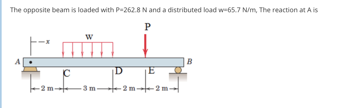
Transcribed Image Text:The opposite beam is loaded with P=262.8 N and a distributed load w=65.7 N/m, The reaction at A is
P
W
B
E
3 m
2 m 2 m
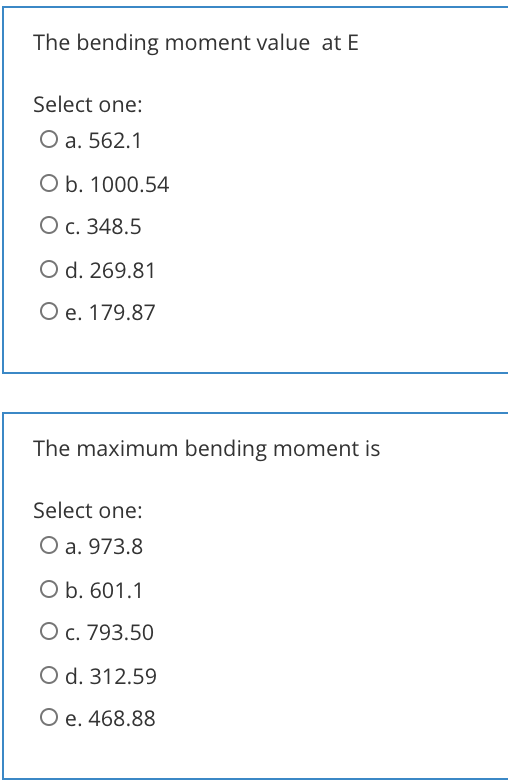
Transcribed Image Text:The bending moment value at E
Select one:
O a. 562.1
O b. 1000.54
О с. 348.5
O d. 269.81
O e. 179.87
The maximum bending moment is
Select one:
O a. 973.8
O b. 601.1
O c. 793.50
O d. 312.59
Ое. 468.88
Expert Solution
This question has been solved!
Explore an expertly crafted, step-by-step solution for a thorough understanding of key concepts.

Step by step
Solved in 3 steps with 3 images

Knowledge Booster


Learn more about
Need a deep-dive on the concept behind this application? Look no further. Learn more about this topic, mechanical-engineering and related others by exploring similar questions and additional content below.Recommended textbooks for you
Mechanics of Materials (MindTap Course List)
Mechanical Engineering
ISBN:
9781337093347
Author:
Barry J. Goodno, James M. Gere
Publisher:
Cengage Learning
Mechanics of Materials (MindTap Course List)
Mechanical Engineering
ISBN:
9781337093347
Author:
Barry J. Goodno, James M. Gere
Publisher:
Cengage Learning