A three-phase, wye-connected, 7 kVA, 230 V synchronous generator has a reactance of 7 ohms per phase. Using the rated kVA and voltage as base values, determine the per-unit reactance. Per unit reactance is Xg = p.u Then refer this per-unit value to a 280 V, 9.5 kVA base. Per unit reactance is Xg = p.u Only use numbers and "." for decimal points.
A three-phase, wye-connected, 7 kVA, 230 V synchronous generator has a reactance of 7 ohms per phase. Using the rated kVA and voltage as base values, determine the per-unit reactance. Per unit reactance is Xg = p.u Then refer this per-unit value to a 280 V, 9.5 kVA base. Per unit reactance is Xg = p.u Only use numbers and "." for decimal points.

Power System Analysis and Design (MindTap Course List)
6th Edition
ISBN:9781305632134
Author:J. Duncan Glover, Thomas Overbye, Mulukutla S. Sarma
Publisher:J. Duncan Glover, Thomas Overbye, Mulukutla S. Sarma
Chapter3: Power Transformers
Section: Chapter Questions
Problem 3.64P: The per-unit equivalent circuit of two transformers Ta and Tb connected in parallel, with the same...

Related questions
Question
Power system analysis
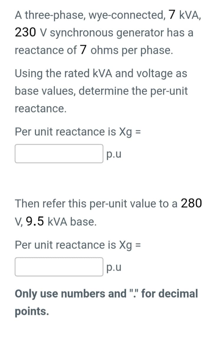
Transcribed Image Text:A three-phase, wye-connected, 7 kVA,
230 V synchronous generator has a
reactance of 7 ohms per phase.
Using the rated kVA and voltage as
base values, determine the per-unit
reactance.
Per unit reactance is Xg =
p.u
Then refer this per-unit value to a 280
V, 9.5 kVA base.
Per unit reactance is Xg =
p.u
Only use numbers and "." for decimal
points.
Expert Solution
This question has been solved!
Explore an expertly crafted, step-by-step solution for a thorough understanding of key concepts.

Step by step
Solved in 2 steps

Knowledge Booster


Learn more about
Need a deep-dive on the concept behind this application? Look no further. Learn more about this topic, electrical-engineering and related others by exploring similar questions and additional content below.Recommended textbooks for you
Power System Analysis and Design (MindTap Course …
Electrical Engineering
ISBN:
9781305632134
Author:
J. Duncan Glover, Thomas Overbye, Mulukutla S. Sarma
Publisher:
Cengage Learning
Power System Analysis and Design (MindTap Course …
Electrical Engineering
ISBN:
9781305632134
Author:
J. Duncan Glover, Thomas Overbye, Mulukutla S. Sarma
Publisher:
Cengage Learning