The rigid bar of negligible weight is supported as shown. The middle helical spring is made of 22 mm diameter steel spring and has an outside diameter of 100 mm with 10 turns and the two side springs are made of 32 mm steel spring and has an outside diameter of 250 mm with 8 turns. Before the load P is applied, the side springs are 25 mm longer than the middle spring. If the applied load P = 15 kN and the rigid bar remains horizontal, determine the stress in each spring. Use G = 83 GPa for steel and G = 42 GPa for bronze.
The rigid bar of negligible weight is supported as shown. The middle helical spring is made of 22 mm diameter steel spring and has an outside diameter of 100 mm with 10 turns and the two side springs are made of 32 mm steel spring and has an outside diameter of 250 mm with 8 turns. Before the load P is applied, the side springs are 25 mm longer than the middle spring. If the applied load P = 15 kN and the rigid bar remains horizontal, determine the stress in each spring. Use G = 83 GPa for steel and G = 42 GPa for bronze.

Automotive Technology: A Systems Approach (MindTap Course List)
6th Edition
ISBN:9781133612315
Author:Jack Erjavec, Rob Thompson
Publisher:Jack Erjavec, Rob Thompson
Chapter3: Basic Theories And Math
Section: Chapter Questions
Problem 16RQ: Weight is the measurement of the earths on an object.

Related questions
Question
The rigid bar of negligible weight is supported as shown. The middle helical spring is made of 22 mm diameter steel spring and has an outside diameter of 100 mm with 10 turns and the two side springs are made of 32 mm steel spring and has an outside diameter of 250 mm with 8 turns. Before the load P is applied, the side springs are 25 mm longer than the middle spring. If the applied load P = 15 kN and the rigid bar remains horizontal, determine the stress in each spring. Use G = 83 GPa for steel and G = 42 GPa for bronze.
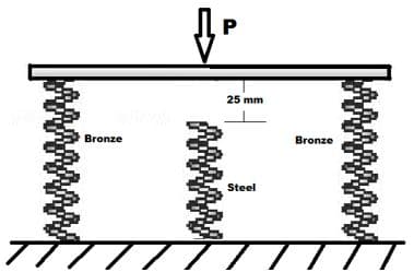
Transcribed Image Text:25 mm
Bronze
Bronze
Steel
Expert Solution
This question has been solved!
Explore an expertly crafted, step-by-step solution for a thorough understanding of key concepts.
Step 1 Given Data and Spring Constant (K) for each spring
VIEWStep 2 Finding Deflection of spring 1 & 2 due to load P without considering Middle Spring
VIEWStep 3 Resisting Load Offered by Spring 1 & 2 due to initial 25 mm Deflection
VIEWStep 4 Net Deflection when Spring 3 Comes in contact
VIEWStep 5 Stresses in each spring due to load carryed by each spring after total deflection
VIEW
Step by step
Solved in 5 steps with 5 images

Knowledge Booster


Learn more about
Need a deep-dive on the concept behind this application? Look no further. Learn more about this topic, mechanical-engineering and related others by exploring similar questions and additional content below.Recommended textbooks for you
Automotive Technology: A Systems Approach (MindTa…
Mechanical Engineering
ISBN:
9781133612315
Author:
Jack Erjavec, Rob Thompson
Publisher:
Cengage Learning

Precision Machining Technology (MindTap Course Li…
Mechanical Engineering
ISBN:
9781285444543
Author:
Peter J. Hoffman, Eric S. Hopewell, Brian Janes
Publisher:
Cengage Learning

Refrigeration and Air Conditioning Technology (Mi…
Mechanical Engineering
ISBN:
9781305578296
Author:
John Tomczyk, Eugene Silberstein, Bill Whitman, Bill Johnson
Publisher:
Cengage Learning
Automotive Technology: A Systems Approach (MindTa…
Mechanical Engineering
ISBN:
9781133612315
Author:
Jack Erjavec, Rob Thompson
Publisher:
Cengage Learning
Precision Machining Technology (MindTap Course Li…
Mechanical Engineering
ISBN:
9781285444543
Author:
Peter J. Hoffman, Eric S. Hopewell, Brian Janes
Publisher:
Cengage Learning
Refrigeration and Air Conditioning Technology (Mi…
Mechanical Engineering
ISBN:
9781305578296
Author:
John Tomczyk, Eugene Silberstein, Bill Whitman, Bill Johnson
Publisher:
Cengage Learning