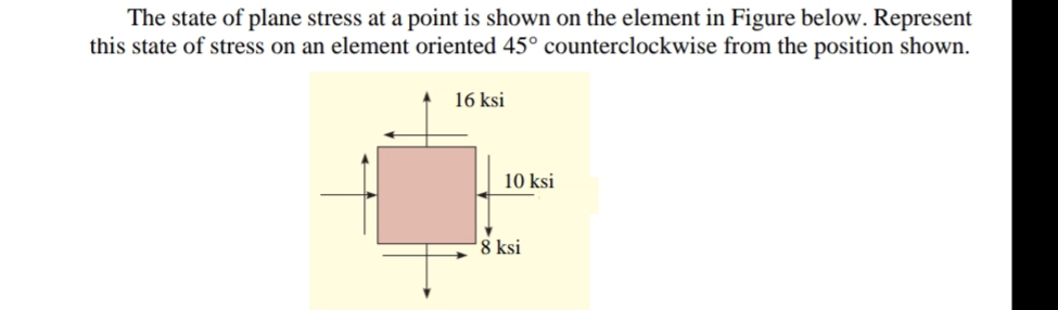
The state of plane stress at a point is shown on the element in Figure below. Represent this state of stress on an element oriented 45° counterclockwise from the position shown. 16 ksi 10 ksi 8 ksi
Q: * The state of plane stress at a point is represented on the element shown in the figure. The…
A:
Q: The cylinder for a hydraulic press has an insidediameter of 300 mm and an outside radius of…
A: Pressure is the intensity of force exerted perpendicularly on an area. Shear stress is the intensity…
Q: A steel pipe assembly supports aconcentrated load of (P = 22 kN) as shown in Figure. The outside…
A: Calculate the moment about point H due to load P. MH=P370 mm×1 m1000 mm=22 kN×1000 N1 kN370 mm×1…
Q: For the assembly shown in the figure below, Determine the state of stress at point A on the cross…
A: To find: The state of stress at point A on the cross section of pipe at section a-a. Given: The…
Q: Due to the applied loading, the element at point A on the solid shaft in Figure is subjected to the…
A: σx=-12 ksiσy=0 ksiTxy=-6ksi σavg=σx+σy2=-6ksi R=(12-6)2+62=8.49 ksi
Q: For the state of plane stress shown in Figure-1. t a) Draw Mohr's circle, b) Determine the maximum…
A: Given data:- σx=-20MPa,σy=90MPa,τxy=60MPa Center of mohr's circle=σx+σy2,0=-20+902,0=(35,0) Radius…
Q: A same circular plate with radius of Ro-560mm and thickness of h=7.42mm is considered here again.…
A:
Q: The state of plane stress at a point is represented on the element shown in the figure below. (a)…
A:
Q: 90 MPA 60 MPA 20 MPA
A: Given that, σx=-20 MPa,σy=90 MPa,τxy=60 MPa, Steps to draw mohr's circle: 1. Take direct stress at…
Q: Determine the equivalent state of stress if an element is oriented 20° clockwise from the element…
A:
Q: 5 mm B. ON A 1900 N 800 M
A: given:
Q: Q1: A certain point in the mechanical part shown in Figure below. Use Mol determine: (a) the…
A: Givenσx=60 MN/m2=60MPaσy=-50MN/m2=-50MPaτxy=30MN/m2=30MPa
Q: For the assembly shown in the figure below, Determine the state of stress at point A on the cross…
A:
Q: A plane element is subjected to stress as shown in below figure. Determine the radius of the mohr…
A:
Q: Determine the principle stresses σ1, σ2, σ3 and their orientation φ, if σx, σy and σz are known as…
A:
Q: Draw Mohr's circle that describes each of the following states of stress shown in Figure 5. 3 ksi 6…
A: given state of stress for element shown in figure a = -12 ksi = - 3 ksi = 0 state of…
Q: Q2 a) Define the term of the neutral axis. b) The steel rod having a diameter of 20 mm is subjected…
A: Given: Diameter, d=20 mmM=400 N-m
Q: At a point on the free surface of a machine part (E = 214 GPa, G = 83 GPa), the state of the stress…
A: Given:σx=-30 MPaσy=15 MPaζxy=25 MPa
Q: An element in plane stress on the surface of an automobile drive shaft shown in Figure Q1(a) is…
A: Given Data The stress acting in the x direction is: σx=-45 MPa The stress acting in the y direction…
Q: B) The Figure shows Mohr's circle for a point in a physical object that is subjected to plane…
A:
Q: For the assembly shown in the figure below, Determine the state of stress at point A on the cross…
A:
Q: Q1) A stat of stress is specified in Figure. By using Mohr's circle determine the normal and…
A: Given:σx=60 MPaσy=-18 MPaζxy=15 MPa
Q: A same circular plate with radius of Ro-560mm and thickness of h=7.42mm is considered here again.…
A:
Q: (7) For the state of plane stress shown in the figure, determine the normal and shear stresses…
A: Given data: The stress in the x-direction is σx=-50 MPa The stress in the y-direction is σy=0 MPa…
Q: The coupling as shown in figure is made from steel has rectangular cross section is designed to…
A:
Q: Determine magnitude of the stresses acting on plane inclined at an angle 0 = 30°, where the vertical…
A:
Q: A rod is composed of three segments as shown and carries the axial loads P1=120 kN and P2=50 kN as…
A:
Q: For the state of plane stress as shown in the Figure: Construct the Mohr's circle. Determine the…
A:
Q: Q1 / If the cross section of the femur can be approximated as a circular tube, determine the state…
A: The free-body diagram of the problem can be sketched as follows, Let the upward normal force at the…
Q: In the figure shown, determine the normal stresses at AD and BC shearing stress at bolt D + ,…
A: Given, tEDC = 10 mmwEDC = 50 mmtAD = tBC = 8 mmwAD= wBC = 36 mmd = 16 mmF = 20 kNLAD = LBC = 0.2 m…
Q: Determine the equivalent stress state of an element oriented 30° clockwise with respect to the…
A:
Q: Determine magnitude of the stresses acting on plane inclined at an angle 0 = 30°, where the vertical…
A:
Q: For the stress state shown in the figure below, use the Mohr’s circle method to determine (a) the…
A: This is a case of pure shear,therefore, Radius of the mohr circle…
Q: A structural member is subjected to a set of forces and moments. Each separately produces the stress…
A:
Q: The state of plane stress at a point is represented on the element shown in the figure below. (a)…
A: Given details: σx=16 MPa, σy=0, ζxy=-10MPa Formula for principal stress: σ12=σx+σy2±σx-σy22+ζxy2…
Q: 934. If an element is subjected to the state of stress shown in Fig. P-934, find the principal…
A:
Q: Three solid cylindrical are welded together as shown in Figure 3. Determine the average normal…
A:
Q: Determine the equivalent state of stress on an element at the same point which represents the…
A: find the normal stress on the element with orientation 31.7 °.
Q: The stress components acting on an infinitesimal element extracted from a plate subjected to the…
A: From the given figure we can observe that the principal stress formula is given by…
Q: An element in plane stress is subjected to stresses: o, = 85 MPa, o, = -30 MPa, and y = 32MPA, as…
A:
Q: Prob. 8.3-4. The state of plane stress at a point is given by the stresses o, = -48 MPa, o, = -24…
A:
Q: For the state of plane stress, stress components are shown on the element in Figure Question 1: a)…
A:
Q: Figure 1.1 shows a thick cylinder with inside radius of r;=94 mm and outside radius ro =136 mm was…
A:
Q: 1) For the state of stress shown in figure, use the Mohr's circle method to determine (a) The…
A:
Q: 2. The L-shaped rod of 50-mm diameter is subjected to the two loadings at its end as shown in FIGURE…
A:
Q: The small steel plate is connected to the right angle bracket by a 10 mm diameter bolt (Figure…
A:
Q: Determine the absolute maximum shear stress of the stress state acting on the element shown in the…
A:
Q: 2.7. The principal stresses at a given point are o1 =10 MPa, ơ2=-100 MPa. Sketch Mohr's circle for…
A: Given data: The positive principal stress, σ1=10 MPa. The negative principal stress, σ2=-100 MPa.…
Q: The frame in (Figure 1) is subjected to a horizontal force of P = 360 N and couple moment. The…
A:
Q: * 'Determine the ox 30 MPa 10 MPa 20 MPa The state of plane stress at a point is represented on the…
A: find the segma x in oriented element.
Trending now
This is a popular solution!
Step by step
Solved in 4 steps with 3 images
- -27 A square plate with side dimension of 2 in. is subjected to compressive stress a and tensile stress The stresses on element A oriented at angle ?? x1=45° aresy1= 75 psi. tx1y1= 275 psi. . Find the state of stress on the element lilt is rotated clockwise to align the x3 axis with the horizontal x axis.At a point on the surface of an elliptical exercise machine, the material is in biaxial stress with t = 1400 psi and trv = —900 psi, as shown in the figure part a. The figure part b shows an inclined plane aa cut through the same point in the material but oriented at an angle ft Determine the value of the angle 6 between zero and 90° such that no normal stress acts on plane aa. Sketch a stress clement having plane aa as one of its sides and show all stresses acting on the clementThe stresses acting on an element are x= 750 psi, y= 600 psi, and xy = 400 psi. Determine the principal stresses and show them on a sketch of a properly oriented element.
- Solve the preceding problem for an element in plane stress on the bottom surface of a fuel tanker (figure part a); stresses are sx= 105 MPa, sy. = 75 MPa, and ??xy= 25 MPa. Determine the stresses acting on an element oriented at an angle ?? = 40° from the x axis, where the angle is positive when counterclockwise. Show these stresses on a sketch of an element oriented at the angle ??.An element on the top surface of the fuel tanker in Problem 7.2-1 is in biaxial stress and is subjected to stresses a = -48 MPa and ay = 19 MPa, as shown in the figure. Using Mohr’s circle, determine the following. (a) The stresses acting on an clement oriented at a counterclockwise angle ?? = 25° from the x axis. (b) The maximum shear stresses and associated normal stresses. Show all results on sketches of properly oriented elements.The polyethylene liner of a settling pond is subjected to stresses ax= 350 psi. a = 112 psi. and = -120 psi, as shown by the plalte-stress element in the figure part a. Determine the normal and shear stresses acting on a seam oriented at an angle 01300 to the element, as shown in the figure part b. Show these stresses on a sketch of an element having its sides parallel and perpendicular to the seam.
- An element on the top surface of the fuel tanker in Problem 7.2-1 is in biaxial .is in the and is subjected to stresses a, = 6250 psi and a. = -1750 psi, as shown in the figure. Using Mohr s circle, determine the following: (a) The stresses acting on an element oriented at a counterclockwise angle ? = 550 from the x axis. (b) The maximum shear stresses and associated norm al stresses. Show all results on sketches of properly oriented elements.The state of stress on an element of material is shown in the figure. Calculate the unit volume change of the element if the stresses x and y. are -20 ksi and 10 ksi, respectively. Assume E = 10,600 ksi and v = 0.33.• - 7.4-7 An element on the surface of a drive shaft is in pure shear and is subjected to stresses ??xy= 2700 psi, as shown in the figure. Using Mohr’s circle, determine the following. (a) The stresses acting on an element oriented at a counterclockwise angle ?= 52° from the y axis. (b) The principal stresses. Show all results on sketches of properly oriented elements.
- Two steel rods are welded together (see figure): the seam is oriented at angle ? = 50°. The stresses on the rotated element are sx1=10 ksi, sy1= -12 ksi, and tx1y1= -5 ksi. Find the state of plane stress on the clement if it is rotated clockwise to align the x3 axis with the longitudinal axis of the rods.An clement m plane stress from the frame of a racing car is oriented at a known angle 8 (sec figure). On this inclined clement, the normal and shear stresses have the magnitudes and directions shown in the figure. Determine the normal and shear stresses acting on an clement whose sides are parallel to the \y axes, that is, determine crv, tr(_, and t, Show the results on a sketch of an clement oriented at B ..4 The stresses on an clement arc known to be sx= 120 MPa, sy= 100 MPa, and txy= 75 MPa. Find the stresses on an inclined section through the element at an angle ? = 45°.