The two-stage compression refrigeration system shown below is used to remove heat from refrigerated space using R-410a as the coolant. The R-410a leaves the evaporator at state 1 and is first compressed in a low-pressure compressor (WLPC=-250 kW) to an intermediate pressure of 933.9 kPa before it is mixed with saturated vapor and then further compressed in a high-pressure compressor to 3000 kPa. Heat is then removed from the R-410a as it passes through the heat exchanger and exchanges heat with cooling water. The R-410a is then expanded in the throttling valve to the intermediate pressure and passed through a type of mixing chamber called a flash chamber where it is separated into a saturated vapor leaving at state 7 and a saturated liquid leaving at state 8. Finally, the liquid is expanded before entering the evaporator at state 9. Note that the mass flow rate of R-410a leaving the mixing chamber is ṁµPC = 10 kg/s. Neglect changes in kinetic and potential energy across all devices and assume the compressors, mixing chamber, flash chamber and throttling valves are well insulated. Refer to the figure for additional information. a) Determine the rate of heat transfer to the R-410a in the Heat Exchanger, QHE- b) Determine the rate of heat transfer to the R-410a in the Evaporator, QE c) Determine the specific enthalpies at states 2 and 3, h, and h3, and the work of the High-Pressure Compressor, WHPC- d) Determine the Coefficient of Performance of the refrigeration cycle. e) Determine the mass flow rate of water through the Heat Exchanger, mw, ana the pump work, W, Water m, T10=10°C W Po= 100 kPa w, T12=20°C Pump P,=P12= 500 kPa T;=25°C Heat Exchanger P,=P3=3000 kPa T=60°C Throttling Valve High-Press. Comp. O mPc=10 kg/s Flash Pe=P,=P=933.9 kPa Mixing Chamber P=P,=P,=933.9 kPa Separator sat. vapor sat. liquid Low-Press. Throttling Valve Wpc=-250 kW Comp. Evaporator to P,=P3=175 kPa X, =0.95
The two-stage compression refrigeration system shown below is used to remove heat from refrigerated space using R-410a as the coolant. The R-410a leaves the evaporator at state 1 and is first compressed in a low-pressure compressor (WLPC=-250 kW) to an intermediate pressure of 933.9 kPa before it is mixed with saturated vapor and then further compressed in a high-pressure compressor to 3000 kPa. Heat is then removed from the R-410a as it passes through the heat exchanger and exchanges heat with cooling water. The R-410a is then expanded in the throttling valve to the intermediate pressure and passed through a type of mixing chamber called a flash chamber where it is separated into a saturated vapor leaving at state 7 and a saturated liquid leaving at state 8. Finally, the liquid is expanded before entering the evaporator at state 9. Note that the mass flow rate of R-410a leaving the mixing chamber is ṁµPC = 10 kg/s. Neglect changes in kinetic and potential energy across all devices and assume the compressors, mixing chamber, flash chamber and throttling valves are well insulated. Refer to the figure for additional information. a) Determine the rate of heat transfer to the R-410a in the Heat Exchanger, QHE- b) Determine the rate of heat transfer to the R-410a in the Evaporator, QE c) Determine the specific enthalpies at states 2 and 3, h, and h3, and the work of the High-Pressure Compressor, WHPC- d) Determine the Coefficient of Performance of the refrigeration cycle. e) Determine the mass flow rate of water through the Heat Exchanger, mw, ana the pump work, W, Water m, T10=10°C W Po= 100 kPa w, T12=20°C Pump P,=P12= 500 kPa T;=25°C Heat Exchanger P,=P3=3000 kPa T=60°C Throttling Valve High-Press. Comp. O mPc=10 kg/s Flash Pe=P,=P=933.9 kPa Mixing Chamber P=P,=P,=933.9 kPa Separator sat. vapor sat. liquid Low-Press. Throttling Valve Wpc=-250 kW Comp. Evaporator to P,=P3=175 kPa X, =0.95

Refrigeration and Air Conditioning Technology (MindTap Course List)
8th Edition
ISBN:9781305578296
Author:John Tomczyk, Eugene Silberstein, Bill Whitman, Bill Johnson
Publisher:John Tomczyk, Eugene Silberstein, Bill Whitman, Bill Johnson
Chapter44: Geothermal Heat Pumps
Section: Chapter Questions
Problem 1RQ: Geothermal heat pumps, or water-source heat pumps, are classified as either _____loop or _____loop...

Related questions
Question
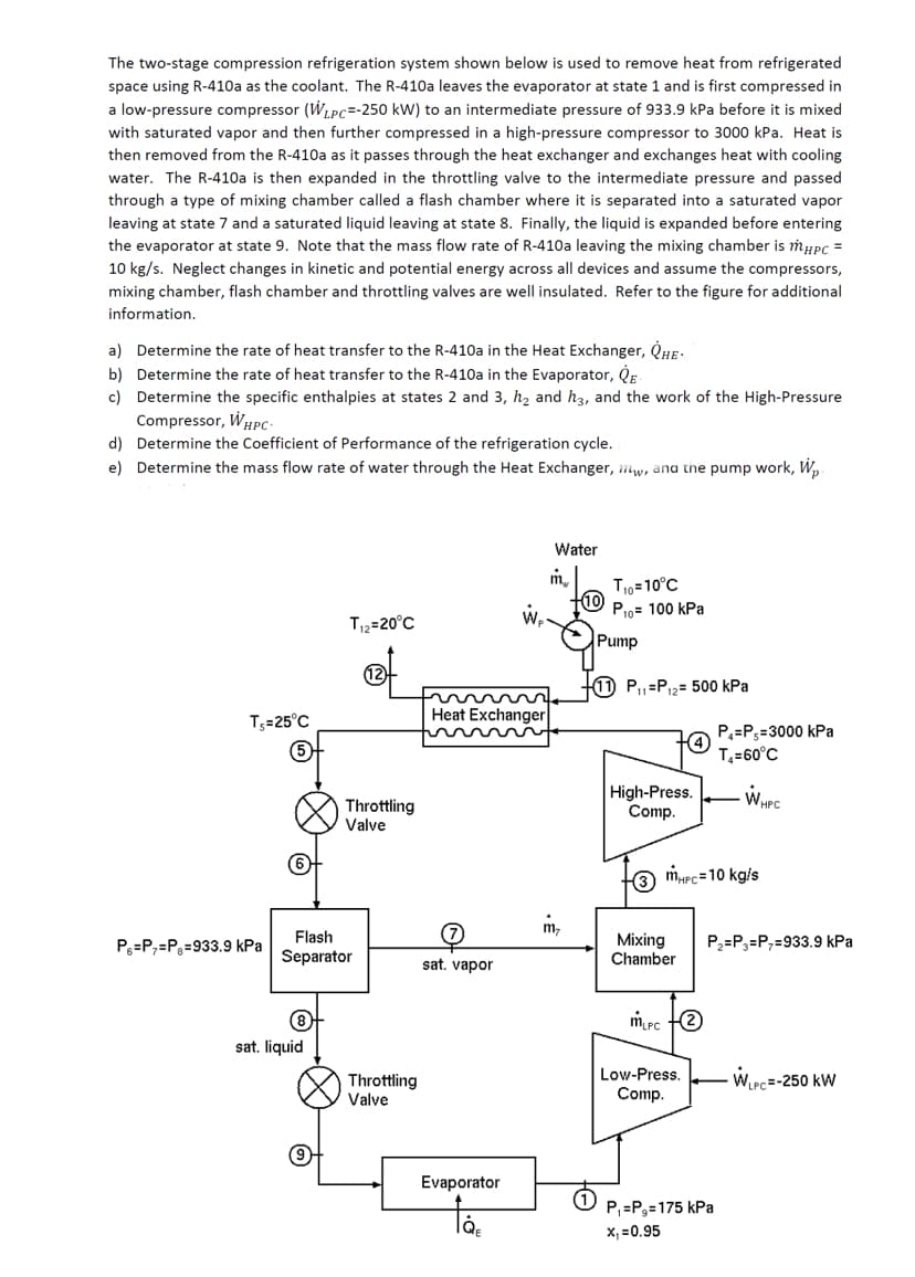
Transcribed Image Text:The two-stage compression refrigeration system shown below is used to remove heat from refrigerated
space using R-410a as the coolant. The R-410a leaves the evaporator at state 1 and is first compressed in
a low-pressure compressor (W, Pc=-250 kW) to an intermediate pressure of 933.9 kPa before it is mixed
with saturated vapor and then further compressed in a high-pressure compressor to 3000 kPa. Heat is
then removed from the R-410a as it passes through the heat exchanger and exchanges heat with cooling
water. The R-410a is then expanded in the throttling valve to the intermediate pressure and passed
through a type of mixing chamber called a flash chamber where it is separated into a saturated vapor
leaving at state 7 and a saturated liquid leaving at state 8. Finally, the liquid is expanded before entering
the evaporator at state 9. Note that the mass flow rate of R-410a leaving the mixing chamber is mypC =
10 kg/s. Neglect changes in kinetic and potential energy across all devices and assume the compressors,
mixing chamber, flash chamber and throttling valves are well insulated. Refer to the figure for additional
information.
a) Determine the rate of heat transfer to the R-410a in the Heat Exchanger, QHE-
b) Determine the rate of heat transfer to the R-410a in the Evaporator, QE
c) Determine the specific enthalpies at states 2 and 3, h, and h3, and the work of the High-Pressure
Compressor, Whpc-
d) Determine the Coefficient of Performance of the refrigeration cycle.
e) Determine the mass flow rate of water through the Heat Exchanger, mw, and the pump work, Wp
Water
m.
T10=10°C
10
w,
P10= 100 kPa
T12=20°C
Pump
12
1 P,=P12= 500 kPa
T3=25°C
Heat Exchanger
P=P3=3000 kPa
T=60°C
Throttling
Valve
High-Press.
Comp.
3 MHPC=10 kg/s
m,
Flash
Mixing
Chamber
P3=P;=Pg=933.9 kPa
P2=P3=P,=933.9 kPa
Separator
sat. vapor
mrc e
sat. liquid
Throttling
Valve
Low-Press.
Comp.
WPc=-250 kW
Evaporator
P, =P3=175 kPa
X, =0.95
Expert Solution
This question has been solved!
Explore an expertly crafted, step-by-step solution for a thorough understanding of key concepts.

Step by step
Solved in 2 steps with 2 images

Knowledge Booster


Learn more about
Need a deep-dive on the concept behind this application? Look no further. Learn more about this topic, mechanical-engineering and related others by exploring similar questions and additional content below.Recommended textbooks for you
Refrigeration and Air Conditioning Technology (Mi…
Mechanical Engineering
ISBN:
9781305578296
Author:
John Tomczyk, Eugene Silberstein, Bill Whitman, Bill Johnson
Publisher:
Cengage Learning
Refrigeration and Air Conditioning Technology (Mi…
Mechanical Engineering
ISBN:
9781305578296
Author:
John Tomczyk, Eugene Silberstein, Bill Whitman, Bill Johnson
Publisher:
Cengage Learning